Take the scenario of two relays in series trying to open AFTER a DC fault has raised the output rail to near Vcc.
One relay tries to open before the other. The instantaneous heat across the just about to open contacts welds the contacts together so that the NO contacts cannot move.
Then a millisecond later, the second relay tries to do the same. It too welds together and the speaker is destroyed.
If a close rated fuse is fitted to the transformer, then it will blow as the capacitors try to recharge. By then the damage is done.
If supply rail fuses are fitted after the main smoothing, then one, or other, of these will blow pretty quickly, and may save a big speaker VC. But these supply line fuses are rarely used.
It has a bridge rectifier and regulator on board.
It is very tolerant of AC input voltage.
For a normal maximum of 28Vdc to the regulator expect to use a 18Vac transformer winding. Use a >=35V smoothing capacitor.
20Vac is a bit too high for a 12V regulator.
Do you own one? As I said, I have two. I tried using it with 16vac and the bridge began to smoke. Works fine with 12vac.
Member
Joined 2009
Paid Member
Here's some practical testing on relays, the key appears to be to switch the speaker to GND under fault conditions.
Speaker DC protection with relays
Another option is to wire one relay in series with the speaker output in NC mode and the other in parallel with the output in NO mode. That way even if the series relay welds together the parallel relay will take out all the fuses and save the speaker. Of course, like a crowbar, the parallel relay is likely to damage something one day.
Another use of the 2nd relay is to put it in the input, switching off the input (if it's the source of the dc error) might add another layer of safety.
I could swap in a SS relay too I suppose.
My power transformer is from an old home theatre receiver so it has, conveniently, a few secondaries including one with 12V ac.
Last edited:
An input mute triggered by DC detect on the output is good.
It can be a fast acting jFET, which will switch before the relays move.
Better to make the mute latching, or very long delay release after removal of the output offset.
I have never done this, but two of my amps have input muting relays.
To date I have never welded an isolating relay, so I'm guessing it is a relatively rare event
No, I have eight kits with the XY PCB.Do you own one? .............
As always I learn how it works BEFORE trying assembly.
I discovered that as standard it has design compromises I do not agree with.
V2. The first two assemblies had minor mods and worked. Got rid of the Darlington and used dual EF.
V3. The next two had more elaborate modifications and worked. Removed R 15k and added another green LED. Changed two of the capacitors.
V4. The next had a further mod that I decided looked too untidy and reverted to version 3. Now the first 5 are all V3.
V5. The next has the relay coils in series for operation upto 30Vac transformer (i.e. any National chipamp). This uses a 317 as regulator and will likely become my adopted version for my last 3. The tracks need alteration BEFORE soldering in the relays.
None of the rectifier bridges smoked, even using 18Vac, with the 7812 and using 29Vac with the 317.
Last edited:
As I said, I bought two. Both needed less than 16Vac to survive. Not sure what your XY PCBs are. I was simply speaking about the one the Bigun showed a picture of. That is the one I have and it seemed to be a good idea to share my experience. If you have a different experience with the same unit, then for sure, tell Bigun to exceed my recommendation. After all, you are the EE here. I'm just a hack.
Mine are not kits. They come assembled. Of course you dissected yours before using them and improved the design. I'm sure you formatted the caps first too. So, rather than correcting my warning, why not just share the changes you made? You'd think I would know by now to steer clear if you but I seem to just keep stepping in the same mud holes. I'll try to be more careful in the future.
debatable.and improved the design.
I changed the design compromises.
In my view this gives an improvement, not everyone would agree.
I have already drawn the V1, V2, V3 pics, ready to photograph for you. Was upstairs checking component values.
Will be able to post soon.
XY speaker delay circuit
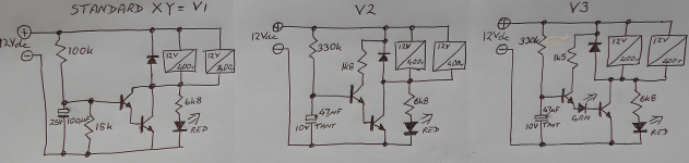
Here is the standard and two modified versions of the XY PCB and kit.
V2 has omitted one 15k. This 15k in V1 increases the delay period. So much so that it can prevent triggering. Check the current through the 100k and then the current through the 15k. A big leakage in the 100uF will prevent any current entering the transistor base. A larger value, 20k to 100k, could be used to adjust the delay period.
In V2 and V3 the delay adjusting resistor can be put back in too. I'd suggest >>30k for periods longer than ~3seconds.
The dual EF ensures the switching transistor is saturated (hFE~10) and drops <0.1V when ON.
The Green LED gives a visual indication of base current into that transistor and raises the voltage on the timing cap by about 1.9V
Attachments
Member
Joined 2009
Paid Member
Mee too. My TGM5 a couple of years back now and my TGM8 (my current and probably last Class AB SS amplifier) both use MOSFET solid state relays for DC protection. I much prefer SS relays. They are rugged, fast, reliable and silent.MOSFET relays are rugged and to my ears totally invisible
I've never used electro-mechanical relay based dc protection before. So recently, I was curious. And I wanted a small pcb to finish off the TGM7 project with minimal fuss. I also thought it would be a good opportunity to take a serious look at the challenges of an electro-mechanical relay based system as I've always shunned them before.
So here we are today, looking at electro-mechanical relays. They are an old technology, well mature and highly engineered. Can we get them to work for us ?
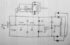
Ignoring concerns about their affect on small signal quality, as far as I can understand it, the real issue is not the relay at all. The issue is the inductive load of the speaker. When the current to the speaker is interrupted the magnetic energy stored in the speaker coil collapses and appears as back emf. This back emf can be very high and it appears across the gap of the relay contacts as they open. This back emf causes breakdown ionization of the air in the gap and allows current flow. The ensuing arc, if high enough current flows, potentially damages the speaker and relay contacts.
The relay coil is another inductive load and we are all familiar with the flyback diode used to protect the semiconductors that are switching the current to the coil. 4QD-TEC Electronics Archive
So why not add catch / flyback diodes to the speaker load too, near the relay contacts, to provide a shunt path for the back emf - thus preventing the arc from striking in the first place ? - see my rough sketch (attached) - I'm talking about D1 and D2.
Attachments
Last edited:
The catch diodes will certainly limit the back emf.
That's why we use them on the output of our power amplifier.
Using them on the other side of the relays may well help. They are often fitted inside the SS relay and inside the mosFET we use for our DIY relay.
Is that enough?
That's why we use them on the output of our power amplifier.
Using them on the other side of the relays may well help. They are often fitted inside the SS relay and inside the mosFET we use for our DIY relay.
Is that enough?
Member
Joined 2009
Paid Member
Is that enough?
The best approach is to test it. I should have ordered an additional board for what is potentially destructive testing. But it does seem on paper to be a workable solution. I even wonder now about adding such catch diodes to the output relays on my commercial home theatre receiver...
The best approach is to test it. I should have ordered an additional board for what is potentially destructive testing. But it does seem on paper to be a workable solution. I even wonder now about adding such catch diodes to the output relays on my commercial home theatre receiver...
Hi, about the diodes in the output of the amplifier, the first circuit I've seen using were AMP ROTEL, (I'm doing a clone this time), at first I thought it was an error of the scheme, but I looked at other schemes / models and there they were, I understand very little of electronics, but in my view they will somehow degrade the audio.
I tried researching this diode array but found nothing, or better, in fact I found a very brief comment from Rod Elliott, but the theme of the page was VI limiter, any cool there is the description:
Editorial Comment (By Rod Elliott)
Some amplifier circuits show diodes connected between the output and the + ve and ve power rails - These are shown in gray in Figure 1 The purpose of These should now be obvious - They will "catch" the spikes generated under the conditions Phil has Explained. These will (hopefully) Prevent the destruction of the output transistors by shunting excess voltage and current back into the power supply Which simply absorbs the energy. The diodes Prevent the amplifier's output voltage from ever Exceeding the supply by more than 0.65 volt or so, and Therefore Prevent reverse biasing of the transistors under fault conditions.
Needless to say, this sonic Provides zero benefit, since the spikes will still Occur, but They Will now be limited to a little over the amplifier's supply voltage. The amp will probably not self destruct, but it will sound just the horrible When driven beyond its current limits .............
Can anyone shed some light on this? 0)
Many power amplifiers use these Supply rail to Output rail protection diodes.
I recommend them since they are cheap and use very little PCB area.
I even add them to PCBs that have omitted them.
I also recommend two more protection diodes, connected from Supply rails to Power Ground. These save an amplifier from mis-connected supply wiring.
I recommend them since they are cheap and use very little PCB area.
I even add them to PCBs that have omitted them.
I also recommend two more protection diodes, connected from Supply rails to Power Ground. These save an amplifier from mis-connected supply wiring.
Member
Joined 2009
Paid Member
I recommend them since they are cheap and use very little PCB area.
Agreed !
Bingu Andre or any of you has a copy of the guide GB150D who can send me, I would be very grateful if you did. after reading the comments so good, I decided to do it, as I said before I have little experience, the guide would help me make the adjustments correctly. thank you so much
Member
Joined 2009
Paid Member
This is the wrong thread for GB150 - do a search for that.
Forgive me, but I already did that and have not found anywhere, all I found is dispesso on several pages and each person has a different setting required.
- Home
- Amplifiers
- Solid State
- TGM7 - an amplifier based on Greg Ball SKA