"A little nonsense now and then is relished by the wisest men"
Although, there must be a line between crazy and inconsiderate.
Any updates on the amplifier?
I think it's interesting that you used a CFP (a "high-end" option) in combination with a simple resistor current source (usually considered a less optimal approach).
Theoretically you don't get a price advantage with this, because you use the CCS transistors in the LTP. So I wonder what the advantages and disadvantages are to this approach.
- keantoken
Member
Joined 2009
Paid Member
You read my mind on the CFP. I have been wondering whether a CCS is needed since the CFP has in my warped way of thinking a 'built in CCS'.
I assume that there are benefits, such as improved PSRR. However, I have yet to find a good enough reason to make my pcb more complex by introducing a CCS. I think it was Uncle Charlie that said something like 'I take things out and if nothing bad happens I leave them out'. That's my reasoning behind the CCS.
For commercial applications, or when designing a project for others to follow (e.g. DX, Supersym), a CCS makes sense as you never know what kind of supply voltage conditions are going to exist in the finished product. That doesn't apply here.
Now I have TGM2 as an interesting comparison with TGM1 where the main difference is only the CFP.
Of course it changes many things subtle, in particular it will change the compensation and this will impact the sonics too.
Progress is slow until I can update my pcb from TGM1. I was holding back until I had solved the 'hum' problem just in case it was pcb related. It isn't pcb related.
The non-linearities of a conventional LTP are caused by variations in Vbe of the two active devices as differential input changes. This creates a flattened S shaped curve, which principally generates third harmonic.
If you place each device into constant current (eg 0.65mA with a 1K Rbe as you do with a CFP) then this problem is solved, and the current swings are taken up by the slave emitter followers, which having collectors at the emitters of the LTP do not add any gross non-linearities.
In this situation the supply to the LTP need not be so pristine, so a resistor is just fine..... you still achieve very close to a straight line transfer function, viz, no H3 and perfect error correction.
Hugh
Bigun said:You read my mind on the CFP. I have been wondering whether a CCS is needed since the CFP has in my warped way of thinking a 'built in CCS'.
Your warped way of thinking is doing you some good. Keep it up.
These are concepts... There is no such thing as warped thinking as long as it applies and agrees with real life.
- keantoken
Member
Joined 2009
Paid Member
Couldn't agree more Keantoken.
So, keeping it simple means adding only the CFP to the design which makes the existing pcb a little more cramped but nonetheless quite doable so I've moved things around and kept the same footprint.
Here's the draft layout (attached) which needs tidying up and then hopefully this weekend will see some etching work.
Attachments
Member
Joined 2009
Paid Member
Some debugging required.
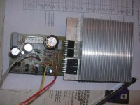
The pcb was made and stuffed. Attached is photo of first TGM2 amplifier.
It's drawing too much current on the +ve rail (via 100R psu resistors), something is wrong - will have to investigate further before allowing those psu rail fuses to be installed.
The pcb was made and stuffed. Attached is photo of first TGM2 amplifier.
It's drawing too much current on the +ve rail (via 100R psu resistors), something is wrong - will have to investigate further before allowing those psu rail fuses to be installed.
Attachments
Very compact , gareth.
How much is "too much" ??
OS
It's drawing too much current on the +ve rail
How much is "too much" ??
OS
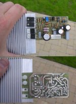
Nice pcb, Gareth.
Sometimes, though, you can make 'em too small, then servicing is an issue - which you soon find out about if you have a problem getting one going!
Too much current generally means bias generator. Check all connections are good, make sure the correct transistors are in all the right places, nearly there....
Cheers,
Hugh
Member
Joined 2009
Paid Member
OS[/i] [B]Very compact said:Nice pcb, Gareth. Sometimes, though, you can make 'em too small, then servicing is an issue - which you soon find out about if you have a problem getting one going!
There's something about compact pcb's that I like, aesthetically that is. And I have to admit to being a bit weird - I find the shapes and patterns of the pcb tracks attractive. Some pcb's have a clinical look, some a messy look and some just look 'right'. I could not find a traditionally symmetric layout that looked 'right' so I ended up with what you see.
AKSA said:Too much current generally means bias generator. Check all connections are good, make sure the correct transistors are in all the right places, nearly there....
UPDATE:
You were right on the money. The bias adjust was just too far off base. I had it set up roughly, but it turned out to be too rough. It's now adjusted and playing in my system for me

It sounds great. First impression is that it's a little cleaner than TGM1. Of course it doesn't have the same kind of H2 injection as TGM1, it uses something a little more subtle. But further listening will have to wait for me to tidy things up. I didn't have the right caps for Cdom (I need to reduce it) or the HF feedback (I need to reduce it a lot). Also, I didn't have the exact resistor values for the LTP collector load so it means that the current balance is out. I see this in the output where my dc offset is of order 100mV and the current flow through the emitter resistors on the output devices is not the same. Nonetheless, I'm not complaining, it looks like it was trying it's best to work straight off the bench.
And listening tests are also hampered because my left ear is at -30dB due to submersion in the local swimming pool for most of Saturday...

EDIT: It's still sounding cleaner, but also with more 'presence', it sounds more grown up than TGM1.
Member
Joined 2009
Paid Member
More listening impressions...
Now I have switched over from my Fostex single full-range to my floorstanding PMC 2-way TL's.
I noticed two main things.
The bass, it's obviously MUCH stronger than the TGM1. It sounds, subjectively, fuller and deeper, more punch.
The treble, clearer but not quite as 'musical' as TGM1. Although I haven't tuned-up the compensation yet.
I'll try to relate this to the design.
The main difference between these designs are the CFP front end. It produces a more linear response over a wider range of input signals. This gives less distortion with larger signal swings, just the thing for improved bass which often has larger amplitude. Less distortion also means less H2/H3. I think H2/3 tends to soften the bass, making it muddy sounding at high volumes because generation of IM products move up into the mids.
I also have less intentional H2 injection in the TGM2. Together with better linearity this means the treble is clearer and the volume can be pushed higher without any loss of clarity. But without as much H2 as the TGM1 it sounds less 'musical'. It seems that there is a tradeoff between the bass and treble between these amplifiers.
All-on-all, the TGM2 is a great sounding amp to my ears ! - and it does this whilst keeping a very simply topology.
edit: the wife prefers TGM2, no question.
Member
Joined 2009
Paid Member
Nice progress, Gareth, you move quickly.
I agree with all your comments; they match my experience precisely.
If some means could be found to increase H2 in TGM2 you might have the best of both worlds! Now there's a challenge.....
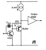
I have not found the same advantage using the CFP in the VAS. (Ah, how I love a TLA!)
Have you considered that a LTP tends to favour odd harmonics over evens? Question: Is there an input configuration which favours evens over odds, like a SE VAS?
Cheers,
Hugh
I agree with all your comments; they match my experience precisely.
If some means could be found to increase H2 in TGM2 you might have the best of both worlds! Now there's a challenge.....
I have not found the same advantage using the CFP in the VAS. (Ah, how I love a TLA!)
Have you considered that a LTP tends to favour odd harmonics over evens? Question: Is there an input configuration which favours evens over odds, like a SE VAS?
Cheers,
Hugh
Member
Joined 2009
Paid Member
Thanks Hugh - I have to keep moving...
I did look at the design with CFP in the VAS and surprisingly didn't see much benefit in the sims. Now I realize that Sims are not the end of the matter but it was surprising. I would have thought that the VAS, with it's large voltage swing on the output would benefit the most from the CFP improving it's linearity. I would also have thought that it would buffer the VAS somewhat from the non-linear load of the output. Maybe the sims are wrong, but then I may also be underestimating the huge benefit that the Bootstrap provides already and the negative feedback due to Cdom helps greatly to reduce local non-linearity and without hurting the sound if it's value is tuned by ear.
There is some H2 injection going on, a vital part of my design philosophy, a bit of 'Hugh Dean Magic' implemented
But it's not as extensive as TGM1. Perhaps it need not be as high because of the inherently cleaner performance of TGM2 ? Can more H2 be added - yes it can, but it requires a different approach than TGM1.
Member
Joined 2009
Paid Member
Originally posted by AKSA Have you considered that a LTP tends to favour odd harmonics over evens? Question: Is there an input configuration which favours evens over odds, like a SE VAS?
That's an interesting (leading) question.
There are input configs with very nice H2 profiles, not symmetrical and therefore not based on the LTP. I see these more often with ClassA amplifiers because some of them use a capacitor at the output and don't need to take advantage of the dc-offset control that an LTP provides. And there are those strange breeds of imbalanced LTPs to think about.
I had started to think about a SE input architecture for a future TGM. It was the 'Nameless' class-A amplifier that MJL21193 is developing that got me thinking about that.
And I haven't finished scratching the surface of JFETs yet. Their square law characteristic is a boon to H2 generation and offer the potential for some tube-sounds for those shy of using glass.
If we could reduce all harmonics and then put back some H2/3 under our own control, we'd have the ideal amplifier, IMO. There seems to be many solutions to this approach, I'm not sure which to settle on yet.
Member
Joined 2009
Paid Member
Hi GEirin,
That's a good question - I have to think back, it's not that obvious why now. At the time I was exploring some improvements over TGM1. Most of my explorations were done using simulations rather than trying it out on a bench. This was / is probably a mistake as simulations don't tell you how things sound. I don't think I found a lot of improvement from the use of the Lender VAS and so I dropped it. If you are the experimenting kind of person I'd suggest a better approach is to try it out on the bench.
My current thinking is that there's more to be gained in terms of improvements to the VAS by introducing a 2nd device. In simulations I didn't find a CFP VAS provided very much benefit. Another option is the Cascode but I shunned that because I had heard people say that they don't like the sound of them - not sure why I paid so much attention to such comments though ! The 3rd option is a cascade and this is what I'm currently thinking about if I were to do a TGM3. It looks good in the sims, allows the compensation capacitor to be driven from both ends.
Sorry, not much of an answer for you
Colin and I tried the Lender. It offered potentially more gain, since not just the base but also the emitter was driven (in antiphase). However, the degeneration at the emitter throws any additional gain away, and sims revealed that gain was identical to a single ended VAS with no degeneration.
Since the increased Zout of a Lender compared to a base drive VAS was higher, we felt that the Lender configuration, though neat to look at, was no advantage.
Instead we moved to a buffered VAS, now driving the output stage from an emitter, not a collector.
This seemed to help, as the output of the VAS became a voltage, rather than a current source. Sims revealed higher OLG, giving more loop gain. Subjectively, we had the feeling dynamics improved.
Hugh
- Status
- This old topic is closed. If you want to reopen this topic, contact a moderator using the "Report Post" button.
- Home
- Amplifiers
- Solid State
- TGM2 amplifier