by keantoken - Well, if you say so. I'll do my future simulations with this in mind.
 lower offset , better ltp balance = lower THD .. almost always. That is if your OPS is "right" .
Stability , is more a function of the dominant poles in the VAS/OPS. So you can run garbage in.. without much affect on stability.
OS
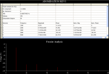
MJL21193 said:Change the input R to 47K and this is the result.
That's 130mV DC offset as opposed to 3mV and THD has climbed considerably.
Increasing the input resistor is not the same as decreasing the feedback resistor. The intention of my suggestion is not to purposely disbalance the LTP, but to simply decrease impedance between the output and LTP, to reduce phase and base current error. The only reason I don't decrease the input resistor just like I do the feedback resistor is for input impedance considerations.
FYI, the fact that increasing the input resistor increases distortion should actually help my point that decreasing the feedback resistor will decrease distortion.
Also, your last attachment does not show an increase in distortion.
ostripper said:
Stability , is more a function of the dominant poles in the VAS/OPS. So you can run garbage in.. without much affect on stability.
OS
Yes, but the LTP does not take feedback from the VAS usually and not in this case. The OPS and VAS phase errors combine and I don't want to combine this with the phase error generated by a 47k resistor.
I think all the hype about super-balancing the LTP is overrated. If you simply know how it works, there's no need to know the rule-of-thumbs (dictum rules are there for beginners and people who don't understand amplifiers too well, and for service technicians who repair amplifiers, to make things simple and efficient).
This said, I've found on the simulator that even if the base currents are in phase with the input and output at low frequencies, this is not the case at frequencies from 1KHz upward with high OLG (you are not only correcting distortion at this point, but phase as well). And if the base currents are not in phase, there is less of a chance you will get any canceling affect from making the impedances on both sides the same. In fact, the source impedance to both sides of any amplifier is ideally zero.
If you want to test my observations, decrease the feedback network by a decade. That is the only way.
- keantoken
PS: Bigun, I'm not trying to make a mess out of your topic. I will stop this if you request.
Member
Joined 2009
Paid Member
Originally posted by keantoken Increasing the input resistor is not the same as decreasing the feedback resistor. The intention of my suggestion is not to purposely disbalance the LTP, but to simply decrease impedance between the output and LTP, to reduce phase and base current error. The only reason I don't decrease the input resistor just like I do the feedback resistor is for input impedance considerations.
I did find an improvement when I decreased the feedback loop resistance in terms of distortion. I also recognize the tradeoff in choosing R1. As with opamps, there is a dc bias current at the non-inverting and inverting inputs so the value of the resistors at each input will result in a dc offset and choosing them to be the same minimizes this. Yet the value of R1 affects greatly the input impedance. Fortunately, I didn't go forward with the Lightspeed attenuator plan because I have so many channels as that would have required a much higher input impedance.
Question: how much dc-offset is bad (as far as my speakers are concerned) ? - I didn't think zero offset was really very necessary ?
Yes, but the LTP does not take feedback from the VAS usually and not in this case.
I do have C6 from the VAS to the feedback node (22pF).
Not at all - I have this thread for two reasons, to act as a kind of 'blog' and to learn from others who participate in it. Constructive debate is strongly encouraged !Bigun, I'm not trying to make a mess out of your topic.
Originally posted by OS better ltp balance = lower THD .. almost always.
This is in fact what I have found in the sims and also believe to be true. Mostly I see the impact on the lowest order harmonics.
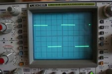
FINALLY... I have my scope up and running. We're looking at TGM1 here of course as TGM2 hasn't been built yet. A couple of borrowed scope probes. I'm afraid the scope and the probes aren't great but they do work. I tried to calibrate the probes as best I could but it was pretty hard to do so. One probe simply would not reproduce the calibrated square wave nicely.
So, hooking the 1kHz scope cal. output to the amplifier (via volume control) and looking at the output with a speaker connected (too loud) I was able to see my first square wave output. We're on 50mV/div with a 10x probe so output amplitude is around 2V pp. My apologies for the poor image, but the waveform looks as clean as the probe will allow - no ringing, rounding or other niggles were obvious.
Attachments
Member
Joined 2009
Paid Member
And I am making progress in tracking down the hum problem.
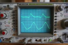
I can see the hum across the speaker terminals. The attached scope plot shows two traces (speaker connected).
The lower trace is the ripple on one of the supply rails, makes a nice reference waveform for the scope trigger. At most we have 2.5div x 5mV/div x10(probe) = 150mV pp (two channels powered up). Timebase is 2ms/div so we're looking at 120Hz, as expected.
The upper trace is the hum across the speaker terminals. It's a bit fuzzy, but I don't think we're seeing oscillations here (none visible on the plot shown on the previous post for example) but rather some general contamination by noise (input is floating). We are looking at around 1.5div x 0.5mV/div x10 (probe) = 7mV peak. It's enough to be annoying.
Attachments
Member
Joined 2009
Paid Member
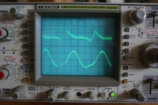
Next stop was to look between speaker return and chasis. In this design the speaker return goes to a start point on the power supply which is lifted from ground via 100R.
It looks like all the hum is developed here. If I temporarily connect the speaker between the output and chasis the hum goes away.
Here's a scope plot of the signal between chasis and speaker gnd return - looks same as previous scope plot doesn't it.
It looks like all the hum is developed here. If I temporarily connect the speaker between the output and chasis the hum goes away.
Here's a scope plot of the signal between chasis and speaker gnd return - looks same as previous scope plot doesn't it.
Attachments
keantoken said:
Also, your last attachment does not show an increase in distortion.
Ahem, a loooong work day at the end of two weeks straight of working everyday (yes, Saturday and Sunday too) plus a few too many barley sandwiches (
) to help me unwind and I'm bound to make more mistakes than I usually do....I have gone back and done a few more sims, lowering the feedback R (and the shunt R proportionately) and found the THD DID drop, by a reasonable margin.
Hold on, I'm pulling my foot out of my mouth...
- did it again, didn't I?Still the problem of DC offset to overcome though.
MJL21193 said:
Ahem, a loooong work day at the end of two weeks straight of working everyday (yes, Saturday and Sunday too) plus a few too many barley sandwiches (
I have gone back and done a few more sims, lowering the feedback R (and the shunt R proportionately) and found the THD DID drop, by a reasonable margin.
Hold on, I'm pulling my foot out of my mouth...
Still the problem of DC offset to overcome though.
Okay. Now tell me point blank, that I'm right, and that I did something right for a change, and that I actually discovered something worth knowing.
This is for my encouragement actually, don't get the wrong idea.
It would be nice to hear someone say that.
In all honesty, I went into the sim myself and tried to reconvince myself of this, but it seems it has different effects on different amplifiers. It actually increased distortion by .00004%, on my (supposedly) .00023% THD Class-A amp
D). Don't have many different subjects to test on.Although it is worthy to note that if it increases stability you can increase OLG for a given Cdom value.
- keantoken
keantoken said:
Okay. Now tell me point blank, that I'm right, and that I did something right for a change, and that I actually discovered something worth knowing.
Coming from me, it might mean little, but here goes:
"You the man, kean!..Booya!!"
Feel better?
This is all simulation, may not play out the same in reality - too many other factors at work. The way is to build it both ways and THD measure both. Could be revealing.
MJL21193 said:
Coming from me, it might mean little, but here goes:
"You the man, kean!..Booya!!"
Feel better?
This is all simulation, may not play out the same in reality - too many other factors at work. The way is to build it both ways and THD measure both. Could be revealing.
Thank you. I feel warm inside now. The icicles will take a while to melt though. Oh no, they're dripping and getting everything wet. >_>
Too bad I can't say much about reality. All I know about reality is that my .000233% THD amplifier is sitting on my breadboard, absolutely not working correctly (oscillates like mad, which is expected, but it doesn't have any gain for some reason and it clips at 1V).
EDIT: Wait a second, my supplies are +-17.5V, and I'm using 25V transistors. No wonder :/
Reality hurts.
Bigun, good luck with you project.
- keantoken
Member
Joined 2009
Paid Member

Out of curiosity, Bigun, how sensitive is your scope, as in V/div?
EDIT: Nevermind, it was in the picture. Duh.
I have a Tektronix 561B from 1964D). It has a 3B4 timebase plugin and a 1A9 differential amplifier plugin.
I can measure voltages down to 10uV. I can measure the ripple of my power supply with no load connected (apart from the 1meg probe impedance). CMRR of this diff. amp is -110 db. I wonder if I could make a hifi amplifier with it?
If they were able to achieve this in 1964 there is no way you should be unsatisfied with what you have now.
Oh well. Now that we have chips, no one has to think about their design. Just plug it in the slots right and it works. :/ That is why I try to do everything in discretes.
- keantoken
EDIT: Nevermind, it was in the picture. Duh.
I have a Tektronix 561B from 1964
D). It has a 3B4 timebase plugin and a 1A9 differential amplifier plugin.I can measure voltages down to 10uV. I can measure the ripple of my power supply with no load connected (apart from the 1meg probe impedance). CMRR of this diff. amp is -110 db. I wonder if I could make a hifi amplifier with it?
If they were able to achieve this in 1964 there is no way you should be unsatisfied with what you have now.
Oh well. Now that we have chips, no one has to think about their design. Just plug it in the slots right and it works. :/ That is why I try to do everything in discretes.
- keantoken
Member
Joined 2009
Paid Member
That depends on the gain of the scope amplifier knob. The normal maximum is 5mV per Div, but you can pull out the centre part of the knob to get a 10X additional gain, giving you 0.5mV per Div. But then the scope probe I have is a 10X which means it attenuates the signal by a factor of 10 before it reaches the scope amplifier.
I'm not complaining, I got it for free
I'm not complaining, I got it for free
Member
Joined 2009
Paid Member
- Status
- This old topic is closed. If you want to reopen this topic, contact a moderator using the "Report Post" button.
- Home
- Amplifiers
- Solid State
- TGM2 amplifier