Bigun said:
Keantoken,
I haven't tried putting the VAS Cascode into the sim yet (maybe tomorrow).
I wasn't trying to push. The question is, will the cascode's relevance to me be enough to make it relevant to you?

When and if you do try it, I am interested in your subjective and/or objective results.
- keantoken
Member
Joined 2009
Paid Member
Well, first off I don't know much about Cascode's. I'm not sure how to implement this. I have made my best estimate as to how to add this into the VAS and to provide it with a stable bias from the -ve rail.
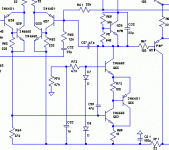
However, I don't see an improvement in the distortion performance. Before I debug this, can you comment on the implementation - schematic attached
However, I don't see an improvement in the distortion performance. Before I debug this, can you comment on the implementation - schematic attached
Attachments
Member
Joined 2009
Paid Member
Bigun said:Before I debug this, can you comment on the implementation - schematic attached
That looks like it will work, though I would put the cascode between the VAS and the rail.
I can't see an advantage to this configuration though. A blameless style EF will most likely do as well or better with less complexity.
Bigun said:Well, first off I don't know much about Cascode's. I'm not sure how to implement this. I have made my best estimate as to how to add this into the VAS and to provide it with a stable bias from the -ve rail.
However, I don't see an improvement in the distortion performance. Before I debug this, can you comment on the implementation - schematic attached
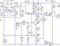
Bigun said:and as an interesting variation I tried this (attached), also no improvement.
Just curious, but the diodes you are using is it diodes or LED’s?
Could you post the voltages on the schematics?
Bigun said:Well, first off I don't know much about Cascode's. I'm not sure how to implement this. I have made my best estimate as to how to add this into the VAS and to provide it with a stable bias from the -ve rail.
However, I don't see an improvement in the distortion performance. Before I debug this, can you comment on the implementation - schematic attached
Personally, I haven't seen much improvement in using a filtered reference for the cascode - as long as the collector voltage of the VAS is steady in comparison with the +-20V that would be there otherwise, you should have an improvement. In my simulations, using a cascoded CFP for the VAS actually increased distortion. Your second schematic, theoretically, would have worse performance, because of the collector voltage of the CFP slave. Then again, maybe we've met the limit of simplistic theory.
I usually feed the VAS cascode with two diodes fed off of the unused side of the LTP, as in my schematic I linked to earlier.
Scratch that, in one of my recent simulations, feeding the cascode off of an LED with a 10u bypass cap results in a decrease in HF distortion. (if you want, I can post my simulation files so you can play with them yourself)
Bigun said:and as an interesting variation I tried this (attached), also no improvement.
Oh, well. When I simulate amps, I cycle through a bunch of possibilities to see what causes the most benefit and what doesn't help. Eventually, there is nothing I can do to make it better. The cascoding tends to be one of the last things I add, so maybe it just has a very small affect (maybe even insignificant).
Why don't you post the specs, such as gain and THD?
Personally, I think you should build it already. Microscopic improvements can only go so far, since the real world is inherently not precise. I think it is a better idea to make a board that accomodates for your selected options and see if there is a significant audible difference.
I've had odd sleep hours all this week, so I have said some odd things. Sorry.
- keantoken
Member
Joined 2009
Paid Member
Originally posted by stinius Just curious, but the diodes you are using is it diodes or LED’s?Could you post the voltages on the schematics?
Stinius, what an insightful question. Yes, the regular LEDs that I used don't offer sufficient voltage drop. I've made this mistake before.

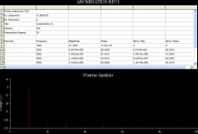
I've re-run the sim with LED's. And I see an improvement in the FFT. It's a not a huge improvement, but a further drop in H2 but not for higher orders.
Member
Joined 2009
Paid Member
Originally posted by keantoken Personally, I think you should build it already. Microscopic improvements can only go so far, since the real world is inherently not precise.
Your absolutely right Keantoken. Bearing in mind that I am on a quest to learn a bit more about amplifiers, trying the Cascode was worthwhile but I won't build a version with a Cascode.
The next step is to remove the bells & whistles, then refine the design, or at least ensure I've captured enough to proceed with a pcb layout.
Member
Joined 2009
Paid Member
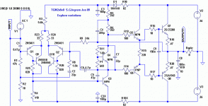
so, here's the updated schematic. The nfb is set for a gain of around 15 which matches the TGM1 (they will all end up in the same box).
Any errors or concerns ?
p.s. I will continue the search for improvements etc. on this amp design as part of my next project:
http://www.diyaudio.com/forums/showthread.php?s=&threadid=146015&highlight=
Any errors or concerns ?
p.s. I will continue the search for improvements etc. on this amp design as part of my next project:
http://www.diyaudio.com/forums/showthread.php?s=&threadid=146015&highlight=
Attachments
What are Q9 and Q10 for? I would delete them. You need to reduce the value of R1, because the bias (base) current of Q1 will give you a large DC offset voltage. Maybe, you don't care, because the amp is AC coupled. I think you need to reduce the value of R4 to better balance the input stage.
Member
Joined 2009
Paid Member
sawreyrw said:What are Q9 and Q10 for? I would delete them. You need to reduce the value of R1, because the bias (base) current of Q1 will give you a large DC offset voltage. Maybe, you don't care, because the amp is AC coupled. I think you need to reduce the value of R4 to better balance the input stage.
I only roughly balanced the LTP by adjusting R4 in the sims since the actual devices are always a bit different. I will recheck the sim to get a closer match as a starting point.
Q9 and Q10 make a big difference to the linearity of the LTP (for the better).
As for R1, I hadn't thought about it's impact on dc offset, I simply retained the value from my previous design. What kind of dc offset is good and bad ? I figure my speakers probably don't care about several 10's of mV ?
Member
Joined 2009
Paid Member
number 47 eh ! 
well I'd better check the total chain first. I've a BluRay player as the source, which I believe is a 10k output impedance. Then I have a 50k pot as a volume control with (golly can't remember) a fixed resistor from the wiper to signal gnd. to turn the linear pot into something more logarithmic. So all of that goes in parallel with the input impedance of the amp.
well I'd better check the total chain first. I've a BluRay player as the source, which I believe is a 10k output impedance. Then I have a 50k pot as a volume control with (golly can't remember) a fixed resistor from the wiper to signal gnd. to turn the linear pot into something more logarithmic. So all of that goes in parallel with the input impedance of the amp.
Member
Joined 2009
Paid Member
Greg,
OK, I checked. The volume control has a 10k fixed resistor from the wiper to signal gnd. So that means the effective input impedance if I use 47k for R1 would be 8k24 and if I use 24k for R1 this drops to 7k. There isn't a huge difference between them so I figure if it works with 8k it will work with 7k.
Probably what is more important is whether either of these options is too low for my source which has a 10k output impedance. But since there will be some series resistance in the volume control the source might well 'see' 10k. The output of my source is 2V so a 10k input impedance nicely brings this down to the right range.
I'll give it a try.
Greg Erskine said:Rule-of-thumb #47 "set R1 equal R9".
I challenge this. It would make sense to make both sides of the LTP as equal as possible, but in the simulator, I have found that lowering R9 (typically by a decade) usually reduces distortion and increases stability.
It might be a convenient option so as to make adjusting easier (because of the offset, you can't just adjust R4 or R3 until the output is at 0).
Is there a something I'm missing?
- keantoken
keantoken said:
I challenge this.
In my simulations and on measurements of my real amps, having these resistors unequal results in DC offset being higher and (in simulation) THD reads higher too.
keantoken said:That's odd. What about stability?
Stability is unaffected, from what I've seen.
- Status
- This old topic is closed. If you want to reopen this topic, contact a moderator using the "Report Post" button.
- Home
- Amplifiers
- Solid State
- TGM2 amplifier


