I read this somewhere but couldn't find a source. I saw a block diagram that I can't find now. Anyway, pin 5 is connected to V+. Does anybody know what pin 5 is for?
I have a chassis, heat sink, dual mono power supply (+/- 30 volts @ 6 A each) ready to go and need some amplifier boards. I was going to whip up something simple. I would like to know what pin 5 is for, though; even though I'm just going to hook it up.
pin 5 on the 7293 is the clip detector logic line
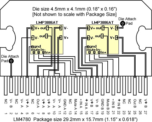
pin 5 on the 3886 is just a parallel to pin 1
Are these (attached) the currently preferred component values for TDA7293 Inverting T-Net?
Has it been auditioned yet?
to be precise, the exact values i auditioned were 10k2 22k1 rather than 22k and 10k, all fixed Rs were 1% CMF RN60 Vishay Dale.
except that zoebel R was 2r7 1w
the bypasses were at the chip pins 100 nf x7r || 220uf low ESR.
bootstrap 220uf.
+/- 25V regulated supply, 4 ohm load.
master and 1 slave.
pot set to lowest offset (was under 1mv) took it out and measured it and found it to be slightly over 10k.
sounded excellent.
there may be values that work even better.
i'd be inclined to try 10k2 instead of the 22k1 along with 200R instead of the 100R.
Last edited:
pin 5 on the 7293 is the clip detector logic line
pin 5 on the 3886 is just a parallel to pin 1
the 3886 die itself has two pads for each rail
so 1 and 5 probably go to different pads on the die
the 3886 die itself has two pads for each rail
so 1 and 5 probably go to different pads on the die
Yes. It would be nice to know what's going on instead of following a cookbook diagram though. Is there an advantage to be gleaned? This is what we do here.
However, the application of the device is so simple that I'm quite confident of good results.
by swinging down i gather this implies sinking (rather than sourcing). it makes a difference because some tube/valve topologies (such as cathode follower) source current ok but don't sink current well. but 2 to 3 ma is not a big deal for parallel 6922 (2 or 4) active loaded in common cathode. probably worth a try. at worst i blow the chip.
surprised that no one questioned the implications for offset. not to worry. something along the lines of Broskie's DC servo to the rescue.
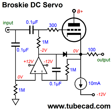
the 1 meg resistorskeep the opamp's sonic signature well away from the tube.
the parts values are 6922-suitable but i would add a type 43 ferrite bead over 300R lead on the grid end or increase the 300R to 681R (mil. spec.)
Last edited:
Yes. It would be nice to know what's going on instead of following a cookbook diagram though. Is there an advantage to be gleaned? This is what we do here.
However, the application of the device is so simple that I'm quite confident of good results.
the strange part is that TI is not consistent in the datasheet's cookbook diagrams. Fig 1 has V+ fed to pins 1 and 5, while the test circuit and single supply circuit just feed pin 1. makes no sense to me.
the strange part is that TI is not consistent in the datasheet's cookbook diagrams. Fig 1 has V+ fed to pins 1 and 5, while the test circuit and single supply circuit just feed pin 1. makes no sense to me.
The fact that it's not hooked up in the test could be a clue, or an oversight. There's a lot going on with the 3886 (it's not just a big op amp) but I want it to drive some difficult speakers (old Bose 301s in my shop). I just repaired, refurbished, and restored my old Nakamichi and it's too nice for the dusty, dirty shop environment. But the mediocre 301s need a big kick in the *** to sound like anything; and they're rated "4-8 ohms"
 which I guess is closer to honesty that some manufacturers. At any rate they need a lot of power and don't even play very loud to boot; the old Nak amp is the only amp I've had that makes them sound at all dynamic. So I'm hoping that the 3886 with its 7 amps max output can do it (Nak claims 14 amps continuous per channel and it never seems to wheeze).
The fact that it's not hooked up in the test could be a clue, or an oversight. There's a lot going on with the 3886 (it's not just a big op amp) but I want it to drive some difficult speakers (old Bose 301s in my shop). I just repaired, refurbished, and restored my old Nakamichi and it's too nice for the dusty, dirty shop environment. But the mediocre 301s need a big kick in the *** to sound like anything; and they're rated "4-8 ohms"
301s yes, i remember those. at the time they were popular my thinking went in the opposite direction from that (Klipsch Cornwall -- a 3-way 15 inch woofer ported beast).
301s yes, i remember those. at the time they were popular my thinking went in the opposite direction from that (Klipsch Cornwall -- a 3-way 15 inch woofer ported beast).
They're shop speakers. They're quirky but hanging in a concrete room, they sound OK - the direct/reflecting feature works great the way I have them set up.
I'd sure rock a set of Klipsch speakers, for sure.
They're shop speakers. They're quirky but hanging in a concrete room, they sound OK - the direct/reflecting feature works great the way I have them set up.
I'd sure rock a set of Klipsch speakers, for sure.
you know, i'm not sure how they would stack up against modern standards. and they take up way too much space!
you know, i'm not sure how they would stack up against modern standards. and they take up way too much space!
Klipsch still makes great speakers. Their lineup is more consumer (wife) friendly. They are more in line with the market demand for relatively compact speakers.
Big speakers sound big - it's hard to fake. I had a pair of home built 15" 3 way monsters employing overstock Eminence drivers. They played real loud with lots of punch.
Of course that's politically incorrect now.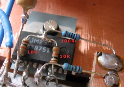
Are these (attached) the currently preferred component values for TDA7293 Inverting T-Net?
Has it been auditioned yet?
if i haven't mentioned it already, one major bit of baggage that comes with the inverting topology is the need to give some thought to limiting the size of the chipamp's feedback loop area. the challenge is that (unlike the situation with a non-inverting chipamp) that loop area includes the interconnect to, and output circuit of, the previous stage. this is finessed easily if the previous stage is right next to the chipamp's input network. so this leads us to either an integrated amp (the linestage colocated with the chipamp) or a non-inverting buffer (again colocated). unless using one of these two solutions or something similar, the chipamp's feedback loop includes the interconnect to the linestage (or other source) and its output network as well, which is not usually a good thing
Yes, the Inverting T-net is especially useful if you wanted it loud; and, that is when you must have the practical/useful tone that generous stability allows. That is what it does, practically.
P.S.
It may be possible to use the two transistor BC5XXc buffer within the feedback loop.
P.S.
It may be possible to use the two transistor BC5XXc buffer within the feedback loop.
Last edited:
Yes, the Inverting T-net is especially useful if you wanted it loud; and, that is when you must have the practical/useful tone that generous stability allows. That is what it does, practically.
P.S.
It may be possible to use the two transistor BC5XXc buffer within the feedback loop.
yes indeed the topology is very clean, robust, and very tolerant of almost anything except the input loop area. to me it can be a fair trade but maybe not for every application, especially nowadays with good capacitors available at reasonable cost for the role of DC blocker in the FB loop of a non-inverting chipamp.
A few tips for a P2P layout.
1. You can remove unwanted pins by bending them a few times. The pins break cleanly where they exit the case.
2. Use smaller resistors for the feedback. For your T-net layout you could even use MRS16 resistors, 3.6 mm 400 mW.
3. Create a small Audio GND point by connecting the input returns and feedback return together.
4. Create a Power GND point close to the output pin. Connect the output return, bypass caps and PSU 0V to this point. Connect a short wire between the Audio GND and the Power GND.
5. Connect the bypass cap supply leads directly to the chip pins.
6. It is very handy to loop the component leads around the chip pins so that they are fixed before soldering.
7. Use flexible wire to prevent stressing the chip pins.
NB: points 3, 4, and 5 in the preceding post have been covered in the build text for some time. although stated slightly differently, if the build text is followed 3, 4, and 5 will be among the results.
the other points can be followed without causing any issues with the rest of the build instructions and are fine suggestions.
the other points can be followed without causing any issues with the rest of the build instructions and are fine suggestions.
Last edited:
- Status
- This old topic is closed. If you want to reopen this topic, contact a moderator using the "Report Post" button.
- Home
- Amplifiers
- Chip Amps
- TDA7293 inverting t-network FB point-to-point