preface --
with all the fake/clone/pull tda72xx chips to sort out, you know what id did? i finally gave up on them and went all-in with TI Overture series parts; avoided the Spike issues by paralleling enough of them for any given application to run well within the safe operating areas shown on the datasheets. have yet to hear a peep out of Spike.
in any event:
this thread is kept alive for posterity and because some of its contents may be useful.
now, i should say that this thread does not reflect what i've done lately with 7293.
since i found almost no performance differences inverting vs non-inverting i've gone back to using the Fly-xy version http://www.ebay.com/itm/111405494862 of Daniel's favorite board as a starting point and to handle the power and output circuitry, but i omit the slave chip and i build the NFB and input circuit point-to-point on the underside of the board with 1k/30k in a conventional NFB loop (not a t-net). the NFB DC-blocking cap is Elna 220uf. the input cap is 3.3uf 400v panasonic poly. (tube preamp). i also use rail-to-rail bypasses for both sets of power inputs (pins 7 to 8 as well as 13 to 15) .22 uf or .47 uf 100v x7r kemet
non-inverting also has the advantage that the mute circuitry works while inverting breaks the mute function for reasons that are obvious if you look at the tda7293 datasheet. and non-inverting avoids the need for a buffer on the input.
end of preface
the purpose of this thread is to have a discussion of the above-captioned topic and related matters.
goals: equal or exceed datasheet performance, low offset (adjustable), easy-to-replicate, reliable & stable, suitable for XLR-end-to-end-balanced applications, no exotic parts, inverting and non-inverting options, opamp buffer option, balanced input option, balanced input option with tube/valve buffer..
so far there have been no reported errors but please do let me know if you spot one (or have an improvement suggestion of any sort, of course!)
SCHEMATICS: the following link contains schematics. the first one is the simplest but the document also includies optional input buffer and alternative more-complex topologies (most of them use t-net techniques):
https://drive.google.com/file/d/0Bz_iSmmoJEGTSTB1WmdJU3llYTg/view?usp=sharing
if you use the buffer it would be after C1 in which case C1 can be smaller valued (ex: 0.47)
some things that are not covered in the schematics:
connect bootstrap capacitor, positive end to chip pin 6, negative end chip pin 12
connect one end of a 100 nf to pin 7*
connect one end of another 100 nf to pin 8*
connect one end of another 100 nf to pin 13*
connect one end of another 100 nf to pin 15*
connect positive end of a 220 uf to pin 7*
connect negative end of another 220 uf to pin 8*
connect positive end of another 220 uf to pin 13*
connect negative end of another 220 uf to pin 15*
join together the unattached ends of capacitors of the 8 preceding steps--this becomes the chip's local power ground star*
the lower end of R2 connects to the power ground star
run power cables to each of pins 7, 8, 13, 15 and the power ground star
connect zoebel network (between power ground star and pin 14)*
BOM -- for inverting t-net version (not including optional input buffer):
1- Authentic TDA7293
1- 50k multiturn cermet minipot (R4 -- used to zero the output DC offset)
1- 3.3uf poly (C1)
2- 10k1 KOA CFS or your favorite type (R1, R3)
1- 22k1 KOA CFS or your favorite type (R5)
1- 10R 1W (R6)
1- gain set (R2) KOA CFS or your favorite type -- choose to select a desired gain > 26db, 100R is typical
1- 100nf x7r 100v (C2 e.g. kemet)
1- 100uf Panasonic FC or Elna 63v (bootstrap cap)
2- FB43 (ferrite beads between input cap and input R)--optional for RFI suppression
4- 220uf 50v low esr (e.g. panasonic FC or a similar nichicon)
4- 100nf 100v x7r (e.g. kemet)
NOTE: you may also also need: stby circuit, PSU, heatsink, case
BOM -- for optional buffer (drawing second row left):
1- 47k KOA CFS or your favorite type (R8)
1-1k0 KOA CFS or your favorite type (R7)
1- NJM4556 or similar unity gain stable audio op amp
proposed optional minimalist diode-based Vs - Vp isolator for power board (drawing top right--one rail shown)
Vp connects at C6 and Vs connects at C8
BOM:
8- diodes each D2 should be schottky. D1 D3 D4: standard 6A? MUR860? BYW98100?
4- 0.1uf 100v x7r (1 at each Vs and Vp pin) C6, C9. C7 and C8 are optional electrolytics
the Vs PSU feeds could be regulated for better PSRR
another approach to vas isolation

from:
http://www.diyaudio.com/forums/attachments/chip-amps/62076d1144680897-tda7293v-tda7294_separate_vpvs.gif
alternate balanced topologies (schematics pic's bottom-most circuits -- the tube-hybrid versions use 6922 or similar)
and lest we forget safety:
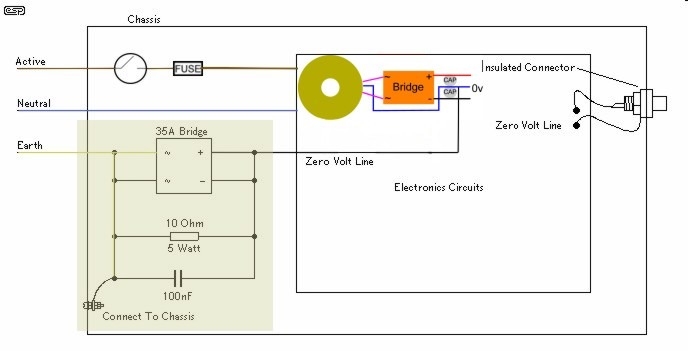
from: http://www.decdun.me.uk/gc/groundlift3.jpg
with all the fake/clone/pull tda72xx chips to sort out, you know what id did? i finally gave up on them and went all-in with TI Overture series parts; avoided the Spike issues by paralleling enough of them for any given application to run well within the safe operating areas shown on the datasheets. have yet to hear a peep out of Spike.
in any event:
this thread is kept alive for posterity and because some of its contents may be useful.
now, i should say that this thread does not reflect what i've done lately with 7293.
since i found almost no performance differences inverting vs non-inverting i've gone back to using the Fly-xy version http://www.ebay.com/itm/111405494862 of Daniel's favorite board as a starting point and to handle the power and output circuitry, but i omit the slave chip and i build the NFB and input circuit point-to-point on the underside of the board with 1k/30k in a conventional NFB loop (not a t-net). the NFB DC-blocking cap is Elna 220uf. the input cap is 3.3uf 400v panasonic poly. (tube preamp). i also use rail-to-rail bypasses for both sets of power inputs (pins 7 to 8 as well as 13 to 15) .22 uf or .47 uf 100v x7r kemet
non-inverting also has the advantage that the mute circuitry works while inverting breaks the mute function for reasons that are obvious if you look at the tda7293 datasheet. and non-inverting avoids the need for a buffer on the input.
end of preface
the purpose of this thread is to have a discussion of the above-captioned topic and related matters.
goals: equal or exceed datasheet performance, low offset (adjustable), easy-to-replicate, reliable & stable, suitable for XLR-end-to-end-balanced applications, no exotic parts, inverting and non-inverting options, opamp buffer option, balanced input option, balanced input option with tube/valve buffer..
so far there have been no reported errors but please do let me know if you spot one (or have an improvement suggestion of any sort, of course!)
SCHEMATICS: the following link contains schematics. the first one is the simplest but the document also includies optional input buffer and alternative more-complex topologies (most of them use t-net techniques):
https://drive.google.com/file/d/0Bz_iSmmoJEGTSTB1WmdJU3llYTg/view?usp=sharing
if you use the buffer it would be after C1 in which case C1 can be smaller valued (ex: 0.47)
some things that are not covered in the schematics:
connect bootstrap capacitor, positive end to chip pin 6, negative end chip pin 12
connect one end of a 100 nf to pin 7*
connect one end of another 100 nf to pin 8*
connect one end of another 100 nf to pin 13*
connect one end of another 100 nf to pin 15*
connect positive end of a 220 uf to pin 7*
connect negative end of another 220 uf to pin 8*
connect positive end of another 220 uf to pin 13*
connect negative end of another 220 uf to pin 15*
join together the unattached ends of capacitors of the 8 preceding steps--this becomes the chip's local power ground star*
the lower end of R2 connects to the power ground star
run power cables to each of pins 7, 8, 13, 15 and the power ground star
connect zoebel network (between power ground star and pin 14)*
BOM -- for inverting t-net version (not including optional input buffer):
1- Authentic TDA7293
1- 50k multiturn cermet minipot (R4 -- used to zero the output DC offset)
1- 3.3uf poly (C1)
2- 10k1 KOA CFS or your favorite type (R1, R3)
1- 22k1 KOA CFS or your favorite type (R5)
1- 10R 1W (R6)
1- gain set (R2) KOA CFS or your favorite type -- choose to select a desired gain > 26db, 100R is typical
1- 100nf x7r 100v (C2 e.g. kemet)
1- 100uf Panasonic FC or Elna 63v (bootstrap cap)
2- FB43 (ferrite beads between input cap and input R)--optional for RFI suppression
4- 220uf 50v low esr (e.g. panasonic FC or a similar nichicon)
4- 100nf 100v x7r (e.g. kemet)
NOTE: you may also also need: stby circuit, PSU, heatsink, case
BOM -- for optional buffer (drawing second row left):
1- 47k KOA CFS or your favorite type (R8)
1-1k0 KOA CFS or your favorite type (R7)
1- NJM4556 or similar unity gain stable audio op amp
proposed optional minimalist diode-based Vs - Vp isolator for power board (drawing top right--one rail shown)
Vp connects at C6 and Vs connects at C8
BOM:
8- diodes each D2 should be schottky. D1 D3 D4: standard 6A? MUR860? BYW98100?
4- 0.1uf 100v x7r (1 at each Vs and Vp pin) C6, C9. C7 and C8 are optional electrolytics
the Vs PSU feeds could be regulated for better PSRR
another approach to vas isolation
from:
http://www.diyaudio.com/forums/attachments/chip-amps/62076d1144680897-tda7293v-tda7294_separate_vpvs.gif
alternate balanced topologies (schematics pic's bottom-most circuits -- the tube-hybrid versions use 6922 or similar)
and lest we forget safety:
from: http://www.decdun.me.uk/gc/groundlift3.jpg
Last edited:
schematic v.0.0
https://drive.google.com/file/d/0Bz_iSmmoJEGTczE5d2JTdVlGZkU/view?usp=sharing
ok let's start with this and assume initially that the circuits (except for local bypassing) for for pins 1, 7, 8, 12, 14, 15 are on one or more separate modules or PCBs.
all fixed resistors are 10k except R2 (which sets the gain), R4 is 50k linear, and C1 is 3.3uf poly.
let's assume local bypassing TBD for pins 7, 8, 11, 15
then at least we need to add the CCS bootstrap (pin 12 or 14 to pin 6) and zoebel (pin14 to SigoutGnd)
COMMENTS?
Last edited:
v.0.1
added zoebel and output conn
https://drive.google.com/file/d/0Bz_iSmmoJEGTOU9FNWdJbllWWEE/view?usp=sharing
added zoebel and output conn
https://drive.google.com/file/d/0Bz_iSmmoJEGTOU9FNWdJbllWWEE/view?usp=sharing
v.0.2
correction to output connector
https://drive.google.com/file/d/0Bz_iSmmoJEGTalYtTXdoN1paWWM/view?usp=sharing
correction to output connector
https://drive.google.com/file/d/0Bz_iSmmoJEGTalYtTXdoN1paWWM/view?usp=sharing
added optional input buffer
u2 is njm4556 or similar
https://drive.google.com/file/d/0Bz_iSmmoJEGTcEdrcnFnRC1Hclk/view?usp=sharing
u2 is njm4556 or similar
https://drive.google.com/file/d/0Bz_iSmmoJEGTcEdrcnFnRC1Hclk/view?usp=sharing
here is what we have so far--
schematic including optional input buffer:
https://drive.google.com/file/d/0Bz_...ew?usp=sharing
BOM (not including optional input buffer):
1- TDA7293
1- 50k multiturn cermet minipot
1- 3.3uf poly
1- 10R 1W
3- 10k1 1% CF RN60
1- gain set R 1% CF RN60 or multiturn cermet minipot, choose to select a desired gain > 20x
1- 100nf x7r 100v (zoebel cap)
1- 220uf FC 63v (bootstrap cap)
2- FB43 (ferrite beads for input cap)
also need: bypasses, mute-stby circuit, PSU, heatsink
here is what we have so far--
schematic including optional input buffer:
https://drive.google.com/file/d/0Bz_...ew?usp=sharing
if you use the buffer it would be after C1 in which case C1 can be smaller valued (ex: 0.47)
BOM (not including optional input buffer):
1- TDA7293
1- 50k multiturn cermet minipot (R4, used to zero the offset)
1- 3.3uf poly
2- 10k1 1% CF RN60 (R1, R3)
1- 22k1 1% CF RN60
1- 10R 1W (R6)
1- 47k (R7)
1- gain set (R2) 1% CF RN60 -- choose to select a desired gain > 26db, 100R is typical
1- 100nf x7r 100v (C2 e.g. kemet)
1- 100uf FC 63v (bootstrap cap)
2- FB43 (ferrite beads between input cap and input R)
2- rail bypassing: 220uf 50v low esr (e.g. panasonic FC) || 100nf 100v x7r (e.g. kemet)
also need: mute-stby circuit, PSU, heatsink, case
optional buffer:
1- 47k (R8)
1- NJM4556
Is there any advantage using separate bypass caps with diodes creating a stable voltage for the low current part of the chip.
Yes, but there is a disadvantage I read about too. Some (all?) of these TDAxxxx chips will latch up and self destruct if the voltage for the low current supply dips much (not very much) below the voltage for the output stage. The workaround is to clamp them together with a fast diode.
I also read that you can make the low current supply voltage a little higher too, as a margin of safety. I would still use a diode clamp. Also, you would want to ensure that funny things don't happen while it's powering up or down; you would want to ensure that the low current voltage supply always tracks higher than the output stage supply.
The most foolproof option is to just clamp them together.
Hopefully somebody with actual experience with these chips will chime in.
illuzn's lengthy series of posts on TDA729x included this solution to both the Vp - Vs isolation issues and bootstrap issues
https://drive.google.com/file/d/0Bz_iSmmoJEGTNFdVNmpBWER1RDQ/view?usp=sharing
he used a voltage doubler to power the "outer" rails (if it blows the amp we can nickname them the "third rails").")
he has zeners and schottkys in there to try keep things sane.
not sure if it's good enough to defend against a failure in a "third rail"
https://drive.google.com/file/d/0Bz_iSmmoJEGTNFdVNmpBWER1RDQ/view?usp=sharing
he used a voltage doubler to power the "outer" rails (if it blows the amp we can nickname them the "third rails").
he has zeners and schottkys in there to try keep things sane.
not sure if it's good enough to defend against a failure in a "third rail"
Last edited:
added a simple optional diode-based Vs-Vp isolation
https://drive.google.com/file/d/0Bz_iSmmoJEGTdnNJT3FPYkdrR2c/view?usp=sharing
https://drive.google.com/file/d/0Bz_iSmmoJEGTdnNJT3FPYkdrR2c/view?usp=sharing
- Status
- This old topic is closed. If you want to reopen this topic, contact a moderator using the "Report Post" button.
- Home
- Amplifiers
- Chip Amps
- TDA7293 inverting t-network FB point-to-point