Hi Andreas
' By the way looking at your pictures, did you removed the feedback capacitors of the internal DAC opamp? 2300/2301 ---> 470 pF '
What will this do ?
Can it change the sound in some way ?
I'll look at the service manual again and check this.
On the tube rectifier idea....I've not the confidence to do another valve project.
My 2 x 6N6P buffer works, is very nice sounding but was the most frightening thing I ever made - I don't really want to try something else using tubes
This is a feedback capacitor creating a 1st order pole at a very high frequency, far beyond the audible range. It is a common technique to suppress noise or oscillations to opamps by limiting the power bandwidth. If the pole is carefully designed, then release the opamp amplitude from unwanted waves, especially in very high frequencies and thus the opamp is working more linear. A balance between the power supply rails filtering (with LC) and small value of feedback caps can give excellent results by smoothing out the sound and cut any advanced or retarded "tails".. I always experiment with some values of feedback caps in my opamp projects for fine tuning.
' By the way looking at your pictures, did you removed the feedback capacitors of the internal DAC opamp? 2300/2301 ---> 470 pF '
The TDA1549 datasheet shows a 1nf cap in these positions, might be worth considering this value if you're not using external opamps. In any case the exact value would maybe not seem to be critical
I have some 720pf silver mica caps sitting around which I intend to try there when I next open it up.
Regards
Pete
Hi Pete
How will you implement that and what are the effects on sound without them ?
You've seen I'm not entirely happy with the upper mids and further up
although my new caps have changed things a little - of that I'm sure.
So have I inadvertently caused some of my problems by stripping it all back too much and then exposing the weaknesses and some noise on the rails with all the grunt ?
Comparing it to my Alpha for a minute - I had the noisy SAA7220 powered and regulated independently and I re clocked the whole player so the 7220 was not distributing 11.289 to anything at all ( it's usual job )
This liquified and cleaned up the whole thing massively - I can still remember the day.
I'm thinking ( and always have ) that the SAA in the CD48 may be doing the same thing as the 7220 ( noise distribution ) and powering it on it's own will provide similar gains.
I could not fathom out the powering of it from the service manual so kind of forgot that route till Andreas stepped in a few days back.
I'll do it once I know how...I've got plenty of spare power to simply add a regulator or two....or three even.
Could be a serious step forward....and who knows...external nicer quality i/v op amps too
Hi Pete
How will you implement that and what are the effects on sound without them ?
You've seen I'm not entirely happy with the upper mids and further up
although my new caps have changed things a little - of that I'm sure.
So have I inadvertently caused some of my problems by stripping it all back too much and then exposing the weaknesses and some noise on the rails with all the grunt ?
Comparing it to my Alpha for a minute - I had the noisy SAA7220 powered and regulated independently and I re clocked the whole player so the 7220 was not distributing 11.289 to anything at all ( it's usual job )
This liquified and cleaned up the whole thing massively - I can still remember the day.
I'm thinking ( and always have ) that the SAA in the CD48 may be doing the same thing as the 7220 ( noise distribution ) and powering it on it's own will provide similar gains.
I could not fathom out the powering of it from the service manual so kind of forgot that route till Andreas stepped in a few days back.
I'll do it once I know how...I've got plenty of spare power to simply add a regulator or two....or three even.
Could be a serious step forward....and who knows...external nicer quality i/v op amps too
Hi Andrew, here you are
")
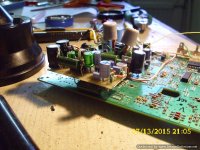
Attach some pictures from the TDA1301 and decoder regulators.
Here below is the technique I followed.
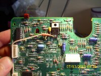
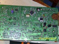
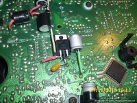
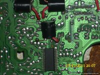
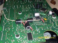
For the TDA 1301 things are simple. I removed the bypass wire 9066. It can be traced in picture 627. Then I removed the bypass capacitor 2013 and fit one Sanyo SEPC 470uF on the solder side (pic 625, 637). Then installed the regulator on the PCB components side (applying an isolation tape just in case) and using the extending legs of the new 2013 capacitor as posts to wire it up. A straight line cable from the PS capacitor + is providing the unregulated voltage.
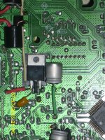
For the decoder chip I've chosen a flat surface on the solder side of the PCB to apply the other reg (pics 625, 626) Hopefully the two power supply lines of the chip are placed very closed, at the common junction where the 2 resistors 3113 and 3115 are connected . I made a small cut to the thin trace carrying the 5V from the PS to above junction, then put on a small piece of isolation tape and install the regulator on it. The regulated out leg is directly soldered on the junction (3113+3115) , the ground leg to the closer plane and supply via cable, as usual... (pics 626, 635, 638) .
Feel free for any questions
chears, Andreas
Attachments
How will you implement that and what are the effects on sound without them ?
I'd just unsolder the original caps and put the silver mica ones in their place, I'm only doing it because I have them sitting around left over from a pack that I bought for something else. Can't imagine that it will make things worse than with the standard.
I've never tried removing them completely, from the data sheet it seems that they make a filter with the internal resistor in the dac so I always assumed that they were needed. Maybe it's that missing filter that's causing your issues.
Regards
Pete
Hi Pete,
silver micas are ideal for such use. I use them for years on whatever is less than 10n..Especially some vintage ones like sangamo,CDE etc. They are very detailed and soft
Hi Pete,
silver micas are ideal for such use. I use them for years on whatever is less than 10n..Especially some vintage ones like sangamo,CDE etc. They are very detailed and soft
Yes, I like them a lot, just not sure how important these 2 filter caps are to the overall sound.
Pete
Hi Andrew, here you are
Attach some pictures from the TDA1301 and decoder regulators.
Here below is the technique I followed.
For the TDA 1301 things are simple. I removed the bypass wire 9066. It can be traced in picture 627. Then I removed the bypass capacitor 2013 and fit one Sanyo SEPC 470uF on the solder side (pic 625, 637). Then installed the regulator on the PCB components side (applying an isolation tape just in case) and using the extending legs of the new 2013 capacitor as posts to wire it up. A straight line cable from the PS capacitor + is providing the unregulated voltage.
For the decoder chip I've chosen a flat surface on the solder side of the PCB to apply the other reg (pics 625, 626) Hopefully the two power supply lines of the chip are placed very closed, at the common junction where the 2 resistors 3113 and 3115 are connected . I made a small cut to the thin trace carrying the 5V from the PS to above junction, then put on a small piece of isolation tape and install the regulator on it. The regulated out leg is directly soldered on the junction (3113+3115) , the ground leg to the closer plane and supply via cable, as usual... (pics 626, 635, 638) .
Feel free for any questions
chears, Andreas
Andreas thank you
- this is excellent and I'm already preparing to do the 1301.I notice you also have the 9055 wire removed too - is that for something else ?
On the decoder chip I can't see or work out where you have cut the trace. Is it underneath the tape?
Can you explain where it is please ?
I have a spare board which I've been studying along with the service manual so I think I can do it once I know where to cut.
Looking forward to doing this !
Not yet tested...The smaller the size, the bigger the trouble ...
Did you try this already ?
Looks like the work of a genius to me - you clearly know exactly what you are doing.
I'd just unsolder the original caps and put the silver mica ones in their place, I'm only doing it because I have them sitting around left over from a pack that I bought for something else. Can't imagine that it will make things worse than with the standard.
I've never tried removing them completely, from the data sheet it seems that they make a filter with the internal resistor in the dac so I always assumed that they were needed. Maybe it's that missing filter that's causing your issues.
Regards
Pete
I laughed out loud at the first sentence - thank you Pete for that detailed explanation....lol
...and on to your answer...I agree and will see what I have in the spares box.
Andreas thank you
I notice you also have the 9055 wire removed too - is that for something else ?
On the decoder chip I can't see or work out where you have cut the trace. Is it underneath the tape?
Can you explain where it is please ?
I have a spare board which I've been studying along with the service manual so I think I can do it once I know where to cut.
Looking forward to doing this !
Andrew, 9055 is a question mark to me also..It's not so long time that completed this mod and nothing reminds me that I removed 2 jumpers at that point. Studying again the Philips CD751 service manual, I concluded that 9055 should have been in place due to powering other TD 1301 gates and also peripheral circuits... I thing I'm getting old
Can you check if this jumper exists into your PCB and also to your CD48 SM? BTW the player reads and plays any disc, at the condition you saw it in pictures ..Yes the trace cut for the decoder is underneath the tape. There's one only thin trace that carries the 5V voltage to the junction of 3113/3115. I cut it at the corner where is turning to get the direction to the power supply
I don't have caps 2300 and 2301 at all - I removed them to facilitate taking wires from the pads of DAC legs 4 and 7 - where these caps were - straight to the output coupling caps.
Is this a mistake ?
I don't like to say anything is a mistake if you're happy with the result.
According to the TDA1549 datasheet these caps in combination with the internal resistors "provides the required 1st-order post-filtering for the left and right channels". The value of the cap determine the 1st order fall-off frequencies.
Marantz typically use 470pf (but with an additional external opamp following. The datasheet suggests 1nf so I guess any value inbetween should be useable. I don't know how myself but I guess there's a formula which will give you the cut-off frequency for a given cap value.
I guess it comes down to whether you feel that the 1st order filtering is needed or not (and if you hear any difference with some caps in and out).
Given your earlier comments it might possibly help with some of the issues that you're hearing.
I'm pretty sure I wouldn't notice one way or the other.
Regards
Pete
' Marantz typically use 470pf (but with an additional external opamp following '
......the additional external op amp which I no longer have so I'm not going to worry about it - glad you posted that Pete.
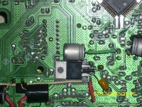
In the attached pic Andreas it looks like you've created your own ground pad to connect the ground of the regulator.
I'm hoping that's correct because I don't have that pad on my board.
Did you scrape away the green insulation coating on the board to solder the regulator ground leg to ?
This is the only question now before I go back in and do this.
The powering of the TDA1301 looks simple enough and...wire link 9055 was already missing - you didn't remove it or have a bad memory
That's the good news anyway !
I'm expecting BIG gains from this....this weekend then
......the additional external op amp which I no longer have so I'm not going to worry about it - glad you posted that Pete.
In the attached pic Andreas it looks like you've created your own ground pad to connect the ground of the regulator.
I'm hoping that's correct because I don't have that pad on my board.
Did you scrape away the green insulation coating on the board to solder the regulator ground leg to ?
This is the only question now before I go back in and do this.
The powering of the TDA1301 looks simple enough and...wire link 9055 was already missing - you didn't remove it or have a bad memory
That's the good news anyway !
I'm expecting BIG gains from this....this weekend then
Attachments
' Marantz typically use 470pf (but with an additional external opamp following '
......the additional external op amp which I no longer have so I'm not going to worry about it - glad you posted that Pete.
I only mentioned the external opamp as the reason Marantz may have used 470pf rather than the 1nf in the datasheet, I didn't mean that the cap isn't needed at all if you don't have the additonal external opamp.
Pete
' Marantz typically use 470pf (but with an additional external opamp following '
......the additional external op amp which I no longer have so I'm not going to worry about it - glad you posted that Pete.
In the attached pic Andreas it looks like you've created your own ground pad to connect the ground of the regulator.
I'm hoping that's correct because I don't have that pad on my board.
Did you scrape away the green insulation coating on the board to solder the regulator ground leg to ?
This is the only question now before I go back in and do this.
The powering of the TDA1301 looks simple enough and...wire link 9055 was already missing - you didn't remove it or have a bad memory
That's the good news anyway !
I'm expecting BIG gains from this....this weekend then
Yes Andrew, that's correct! I created the pad by scratching the green coat.
I guess you have already found the thin 5V trace to cut, in order to supply independently the decoder chip. Big thanks also for the good news regarding that scary 9055 jumper
 I 'm going to cancel the examine appointment with my doctor
A small decoupling capacitor soldered to the input of each one regulator will guaranty the filtering of any noise would picked by the bypass cables and also helps the regulator to work more linear. Values from 1-5 uF tantalum or 10 uF electrolytic are more than enough . For the ideal setup you can add in parallel to above a bi polar 100-220nf polyester, Wima or MKP.. But I guess you already familiar with such setups.
Good luck with your new project!! I trust you will not regret it!!
Yes Andrew, that's correct! I created the pad by scratching the green coat.
I guess you have already found the thin 5V trace to cut, in order to supply independently the decoder chip. Big thanks also for the good news regarding that scary 9055 jumper
Hahahaha
A small decoupling capacitor soldered to the input of each one regulator will guaranty the filtering of any noise would picked by the bypass cables and also helps the regulator to work more linear. Values from 1-5 uF tantalum or 10 uF electrolytic are more than enough . For the ideal setup you can add in parallel to above a bi polar 100-220nf polyester, Wima or MKP.. But I guess you already familiar with such setups.
Good luck with your new project!! I trust you will not regret it!!
Thanks for the encouragement - instructions are understood Captain48
1 regulator capped and ready to go....hic...wine.
I'll do the other tomorrow
I've had a dry run on a spare board and it's all gone ok.
I'll do it for real tomorrow on my good player now I know how it works out.
Andreas - where you've changed the cap to SEPC on the tda1301 I can actually leave the original blue Philips axial cap in it's place and just connect the positive of the regulator to that can't I ?
I don't have any low esr specials left - which is a pity
Apart form that I'm ready to go and looking forward to it.
The problem is the more you've already done to a player the more you must remove to access the damn board - and remember how you did it in the first place !
It used to take only minutes to strip now it's probably 20 - slight exaggeration maybe but you know what I mean.
Tomorrow is also a good time to fit the 3 half watt 3R3 Shinkohs around the dac chip too - they may run cooler I suppose if the now available extra current bothered the smaller original resistors.
This is probably completely wrong too ( before someone tells me ) as I know there's no more current being drawn by the dac chip irrespective of the current available - but I'm thinking maybe extra headroom ?
Anyway they're just better resistors - and they're going in.
I'm sure there'll be a massive difference....hahahahaa NOT
Last edited:
- Home
- Source & Line
- Digital Source
- TDA1549 - Marantz CD48