Tda1541a non-o/s DAC PCB
dear Kuei Yang Wang & peranders,
My tube ouput stage had three method to choice.
one is 6dj8 SRPP which was Thorsten's advise to compensate the little bit lack of bass for the Non-O/S DAC. I added two more is the PCB can use 6C45 or EC86,88 ( set jumper) output.
The last one was use resisters to lower the HV than use the 6DJ8 for LV buffer use.
Dear Peranders
the performance between the NON-O/S & the up-sampling ( 24/96/192) was different. I think this is not easy to judge which one is better.
Tea or coffee, depends on the taster.
this is my opinion.
thnaks
thomas
Tda1541a non-o/s DAC PCB.
Dear all,
I hope this Twin TDA1541A OFC FR4 PCB with all the parts will satify much more digital DIyer's desire.
Due to many people ask for the kits or PCB.
I gurantee that if my PCB ( 2mmOFC FR4 PCB ) & parts
Resisters : Dale, CGW, matsushita & non-inductive IRC resisters.
Optional is RMA.
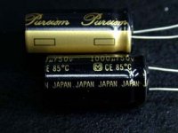
Capacitors : all were OS-con & Elna RJJ low ESR , Matsushita silver brand & pureism.
Decouple cap is philips Blue box 63V 0.22uf. Output cap standard is ERO Cap.
If parts not as the list.
100% money Back GURANTEE.
photos was lst I decide use the 50V 10uf in the power supply part use. Panasonic audio grade OFC lead out Audio cap.
PUREISM
thanks
thomas
Dear all,
I hope this Twin TDA1541A OFC FR4 PCB with all the parts will satify much more digital DIyer's desire.
Due to many people ask for the kits or PCB.
I gurantee that if my PCB ( 2mmOFC FR4 PCB ) & parts
Resisters : Dale, CGW, matsushita & non-inductive IRC resisters.
Optional is RMA.
Capacitors : all were OS-con & Elna RJJ low ESR , Matsushita silver brand & pureism.
Decouple cap is philips Blue box 63V 0.22uf. Output cap standard is ERO Cap.
If parts not as the list.
100% money Back GURANTEE.
photos was lst I decide use the 50V 10uf in the power supply part use. Panasonic audio grade OFC lead out Audio cap.
PUREISM
thanks
thomas
Attachments
Re: Tda1541a non-o/s DAC PCB
Konnichiwa,
I suggested SRPP primarily for the good linearity, not to give "bass".
Mr. Glass of Aquablue wrote a lengthy article on why the TDA1541 non-oversampling was "terrible". Yet he removed an essential function from my filter circuit and choose a very non-linear analogue stage (instead of my very linear one). The result was terrible. Just as on a few other occasions when he took a design of mine and "improved" it.
What happens with a non-linear analog stage is that the whole RF noise intermodulates with the signal and folds back into the audible range. Making the analogue amplification very linear is important for non oversampling DAC's.
Sayonara
Konnichiwa,
siu sin man tho said:My tube ouput stage had three method to choice.
one is 6dj8 SRPP which was Thorsten's advise to compensate the little bit lack of bass for the Non-O/S DAC.
I suggested SRPP primarily for the good linearity, not to give "bass".
Mr. Glass of Aquablue wrote a lengthy article on why the TDA1541 non-oversampling was "terrible". Yet he removed an essential function from my filter circuit and choose a very non-linear analogue stage (instead of my very linear one). The result was terrible. Just as on a few other occasions when he took a design of mine and "improved" it.
What happens with a non-linear analog stage is that the whole RF noise intermodulates with the signal and folds back into the audible range. Making the analogue amplification very linear is important for non oversampling DAC's.
Sayonara
Tda1541a non-o/s DAC PCB.
dear Kuei Yang Wang,
I agree for your opinions. So I reserve 3 method of the tube output stages in the tube output PCB.
The user can use ad844 output stage with the 6dj8 low voltage buffer to output.
Otherwise if they did not like tube output stage. The output PCB was same as a pre-amp PCB. U can choose RC couple or choose 6c45, EC86,ec88 than use pre-amp output 10K or 20K : 600ohm for transformer output.
So, nothing about PCB will waste. Certainly DAC can combine the pre-amp output transformer with the DAC.
But this will decide by the user.
thanks for your opinions about the linear analog stage. I face this problem during design this PCB & solve already.
thnaks
thomas
Re: Tda1541a non-o/s DAC PCB.
Let me understand
Do you mean that you could provide the PCB as well as the parts to DIYers ?
How much it costs ?
siu sin man tho said:Due to many people ask for the kits or PCB.
I gurantee that if my PCB ( 2mmOFC FR4 PCB ) & parts
Let me understand
Do you mean that you could provide the PCB as well as the parts to DIYers ?
How much it costs ?
Tda1541a non-o/s DAC PCB.
Dear ZERS,
thanks for your questions.
I prepare to benefit to all diyers that include all parts.
Resisters : Dale, CGW, Matsushita & non-inductive IRC resisters.
Optional is RMA.
Capacitors : all were OS-con & Elna RJJ low ESR , Matsushita silver brand & pureism.
Elna non-polar is optional.
Decouple cap is philips Blue box 63V 0.22uf. Output cap standard is ERO Cap.
Optional is ERO KT 1803 serious 0.47uf 250v.
Two TDA1541a, two AD844 & one CS8414 or 8412 which up to the diyers choice.
If parts not as the list.
100% moneyBack GURANTEE.
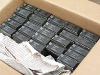
I had large stock of TDA1541a on hand from philips factory which was spare parts.
the two R-core power transformers was optional.
one is for digital board & one is for analog & HV use.
thanks
thomas
Dear ZERS,
thanks for your questions.
I prepare to benefit to all diyers that include all parts.
Resisters : Dale, CGW, Matsushita & non-inductive IRC resisters.
Optional is RMA.
Capacitors : all were OS-con & Elna RJJ low ESR , Matsushita silver brand & pureism.
Elna non-polar is optional.
Decouple cap is philips Blue box 63V 0.22uf. Output cap standard is ERO Cap.
Optional is ERO KT 1803 serious 0.47uf 250v.
Two TDA1541a, two AD844 & one CS8414 or 8412 which up to the diyers choice.
If parts not as the list.
100% moneyBack GURANTEE.
I had large stock of TDA1541a on hand from philips factory which was spare parts.
the two R-core power transformers was optional.
one is for digital board & one is for analog & HV use.
thanks
thomas
Attachments
Tda1541a non-o/s DAC PCB.
Dear peranders,
the sample of the FR4 OFC PCB sample (one set) I post to U already.
U will collect after one weeks.
U ask me that I produce kit or not.
I had three kits.
1.2a3 SE kit (OPT was japan spec but OEM from china)
Branwidth for kit is 20Hz~45kHz -2db. 65ma Z11/M6 core.
Power transformer all use z11/m6 core so very slient & steady temperature with below 45 degree with 8 hours working.
Room temperature is 33 degree.
2.EL34 SE kit. same as above.
3.45 SE kit. same as above.
4.ECL82 use c-core opt.
5.ECL86 use c-core opt.
thanks
thomas
any questions pls email to me.
thomas@diyaudiocraft.com
Attachments
Tda1541a non-o/s DAC PCB.
Dear all.
this two website was the reference material for me to reference.
http://hjem.get2net.dk/torbenk/
http://users.podolsk.ru/boga/DAC.html
But some parts no I was change after I funish the protype & test. Special is the I/V output stage. The tube output stage I was combine with 6C45/Ec86/EC8010,6DJ8 SRPP & 6Dj8 buffer. Which can use jumper to set up by the user.
VERY FLEXIBLE!!!
For example, If U use the AD844 directly ouput.
( A- board is the digital board + C-board AD844 output stage)
the remain B-board PCB can use as the pre-amp use.
6C45 or ec86 all had very low plate resistance. U can change it from cap couple to 10K/20K: 600ohm pre-amp output trans.
The U waill not wate the PCB, another pre-amp was on your hand.
U got a pre-amp with 6C45 or EC86.
thanks
thomas
Tda1541a non-o/s DAC PCB.
Hi,
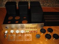
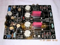
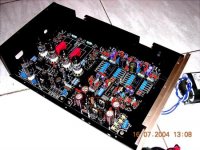
The outlook of A-Board ( digital Part Board) was finish.
I will finish the tube output PCB Board( B-Board) & AD844 OP-amp (C-Board) ASAP.
The enclose black material was contain Graphite Carbonate so its Black in colour with smooth surface. This is I ask for the computor PCB factory & answer to me.
All the parts U see in the photos will same as the supply kits.
Which as I say. 100% GURANTEE money Back if not same.
Very thanks----Happy Diy
thomas
thomas@diyaudiocraft.com
Hi,
The outlook of A-Board ( digital Part Board) was finish.
I will finish the tube output PCB Board( B-Board) & AD844 OP-amp (C-Board) ASAP.
The enclose black material was contain Graphite Carbonate so its Black in colour with smooth surface. This is I ask for the computor PCB factory & answer to me.
All the parts U see in the photos will same as the supply kits.
Which as I say. 100% GURANTEE money Back if not same.
Very thanks----Happy Diy
thomas
thomas@diyaudiocraft.com
Attachments
Tda1541a non-o/s DAC PCB.
Dear all,
the power transformers for this kit was pass the 48 hours stable test already. Temp stable approx 40 degrees temperature.
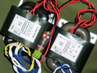
pls take a look for this two power transformers.
PLS know that this two power trans is optional,will not follow with this kit.
But >>>>> I also a diyer, I hope my product can benefit more diyers too.
so I lower my magrinal profit...... really.
This pair power trans one is 30 watts, one is 40 watts.
All had copper foil ground to lower the leakage.
Left hand side XFR-40 one is for tube output stage use.
one winding 6.3V for 6X4 rectifier tube.
another 6.3V winding is for 6DJ8, 417A,404A & ec88,86,8010 use.
The 220~0~220 is for HV use. If u use 6DJ8 buffer, U can use the large watt resisters to drop the voltage.
Right hand XFR-30 is only for digital parts use.
This means this kit will seperate to two power transformer to lower the noise, more stable & higher S/N ratio.
I will sell USD 43 per pairs only with the kit but must added some postage. Kit only will free of charge for posatge.
At least is if the diyer willing to pay USD 10 more, I will change the Output caps to ERO KT1803 & the diode change to MBR 160 or Schottky series
P.S. ... the construction menu I was writing, will link to my web this several days with full support. Easy & continous amend the parts change with different performance.
hope this can help.
thanks
thomas
thomas@diyaudiocraft.com
Dear all,
the power transformers for this kit was pass the 48 hours stable test already. Temp stable approx 40 degrees temperature.
pls take a look for this two power transformers.
PLS know that this two power trans is optional,will not follow with this kit.
But >>>>> I also a diyer, I hope my product can benefit more diyers too.
so I lower my magrinal profit...... really.
This pair power trans one is 30 watts, one is 40 watts.
All had copper foil ground to lower the leakage.
Left hand side XFR-40 one is for tube output stage use.
one winding 6.3V for 6X4 rectifier tube.
another 6.3V winding is for 6DJ8, 417A,404A & ec88,86,8010 use.
The 220~0~220 is for HV use. If u use 6DJ8 buffer, U can use the large watt resisters to drop the voltage.
Right hand XFR-30 is only for digital parts use.
This means this kit will seperate to two power transformer to lower the noise, more stable & higher S/N ratio.
I will sell USD 43 per pairs only with the kit but must added some postage. Kit only will free of charge for posatge.
At least is if the diyer willing to pay USD 10 more, I will change the Output caps to ERO KT1803 & the diode change to MBR 160 or Schottky series
P.S. ... the construction menu I was writing, will link to my web this several days with full support. Easy & continous amend the parts change with different performance.
hope this can help.
thanks
thomas
thomas@diyaudiocraft.com
Attachments
Tda1541a non-o/s DAC PCB..
Hi all,
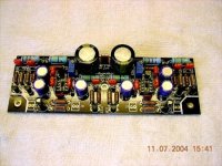
the B board ( tube buffer & I/V output stage PCB was parts fit & finish) All parts will follow with the PCB ( kit)
But I discover a small mistake, 2 legs of the 6X4 layout was inverse. this small mistake U must change by youself. Others nothing with very low noise.
thnaks
thomas
Hi all,
the B board ( tube buffer & I/V output stage PCB was parts fit & finish) All parts will follow with the PCB ( kit)
But I discover a small mistake, 2 legs of the 6X4 layout was inverse. this small mistake U must change by youself. Others nothing with very low noise.
thnaks
thomas
Attachments
Tda1541a non-o/s DAC PCB.
Dear,
all the three PCB with parts were funished already. Today I collected the chassis already.
Its use Motive Car ( private Car ) Paint method to handle the surface of the chassis with 1cm thick aluminium facelet were on my hand, Tonight I will good fit all into the chassis.
Pls give me one more day. U will see tomorrow.
But if U like to buy all, pls considerate the postage.
I weight them all already.
Total approx 8kg full set.
The next question is I will only sell 20 sets in this price, over this amount I will return the original price for USD 230 per set but I will same include postage to buyer.
Pls considerate over 300 pcs of HQ parts I cannot maintain in too low price.
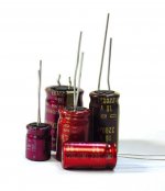
this several days I was testing for this type caps. I would like to know the different bwtween OS-con & Elna-con polar.
Don't worry about the price. I was loacl dealer/reseller of several japan product in hong kong. so I can maintain kits in good price that parts will more cheaper that U buy overseas.
DIY is my hobby, I would like to benefit to more diyers.
Hope U will like them.
thanks
thomas
Dear,
all the three PCB with parts were funished already. Today I collected the chassis already.
Its use Motive Car ( private Car ) Paint method to handle the surface of the chassis with 1cm thick aluminium facelet were on my hand, Tonight I will good fit all into the chassis.
Pls give me one more day. U will see tomorrow.
But if U like to buy all, pls considerate the postage.
I weight them all already.
Total approx 8kg full set.
The next question is I will only sell 20 sets in this price, over this amount I will return the original price for USD 230 per set but I will same include postage to buyer.
Pls considerate over 300 pcs of HQ parts I cannot maintain in too low price.
this several days I was testing for this type caps. I would like to know the different bwtween OS-con & Elna-con polar.
Don't worry about the price. I was loacl dealer/reseller of several japan product in hong kong. so I can maintain kits in good price that parts will more cheaper that U buy overseas.
DIY is my hobby, I would like to benefit to more diyers.
Hope U will like them.
thanks
thomas
Attachments
Thomas,
The PCB look really nice, however unlike the rest of y'all I'll stick with companies like Burr Brown and Analog Devices that know how to design ADC's and DAC's. Also, I just don't care for delta sigma implementation which are true one bit converters and I have alway though the bass from them was a little weak.
Also, let not for get the SPDIF transmission path design and it's clock. This is extreemly important to the sound and performance of the DAC. Of course DAC's are very sensitive to power supply noise and poor grounding. That just a start.
jewilson said:Thomas,
The PCB look really nice, however unlike the rest of y'all I'll stick with companies like Burr Brown and Analog Devices that know how to design ADC's and DAC's.
jewilson said:Also, I just don't care for delta sigma implementation which are true one bit converters and I have alway though the bass from them was a little weak.
And what are those companies doing in the recent years?
jewilson said:Also, let not for get the SPDIF transmission path design and it's clock. This is extreemly important to the sound and performance of the DAC. Of course DAC's are very sensitive to power supply noise and poor grounding. That just a start.
Is this a comment to this PCB?Tda1541a non-o/s DAC PCB..
Dear ALL,
ALL FUNISH.
IF U CHOOSE MY KIT, added optional pair power transformers & the Private car silver shiny base with black colour aluminium chassis.
U will get this.
hope all will love it.
thomas@diyaudiocraft.com
thanks
thomas
Dear ALL,
ALL FUNISH.
IF U CHOOSE MY KIT, added optional pair power transformers & the Private car silver shiny base with black colour aluminium chassis.
U will get this.
hope all will love it.
thomas@diyaudiocraft.com
thanks
thomas
Attachments
Tda1541a non-o/s DAC PCB.
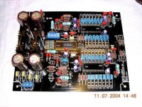
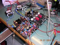
Dear all,
more photos without the chassis.
thanks
thomas
thomas@diyaudiocraft.com
Dear all,
more photos without the chassis.
thanks
thomas
thomas@diyaudiocraft.com
Attachments
- Status
- Not open for further replies.
- Home
- Source & Line
- Digital Source
- TDA1541A PCB finish.