till said:none of all you old philips DAC fanatics did try this?
Huh?
What?
Me?

My dacs have been quiet, I've been fiddling with phonostages and amps lately.
Bernhard has been fiddling with clocks.


Hi till,till said:And it works with schemtaic shown in #90!
now for the discrete inverter for the - DAC
did you built it or this is just a simulation ?
Did you built this one ?

Hi,
Has anyone read the papers on the attachment?
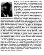
Did RUDY J. VAN DE PLASSCHE work on the tda1541 ?
I compared the datasheets of the tda1541a, and tda1543 to try and see what the main differences were.
From this thread:-
-5 to -15V powers oscilator, and DEM circuits. (on the tda1541a datasheet they are decoupled to each other to ground)
I'm sure I would not understand the papers but i'm sure someone out there could translate!
Then maybe DEM reclocking could be worked on http://www.diyaudio.com/forums/showthread.php?s=&threadid=11949&highlight=
Kind regards,
Ashley.
Has anyone read the papers on the attachment?
Did RUDY J. VAN DE PLASSCHE work on the tda1541 ?
I compared the datasheets of the tda1541a, and tda1543 to try and see what the main differences were.
From this thread:-
-5 to -15V powers oscilator, and DEM circuits. (on the tda1541a datasheet they are decoupled to each other to ground)
I'm sure I would not understand the papers but i'm sure someone out there could translate!
Then maybe DEM reclocking could be worked on http://www.diyaudio.com/forums/showthread.php?s=&threadid=11949&highlight=
Kind regards,
Ashley.
Attachments
Has anyone build this voltage-level circuit for 1541's I2S yet????
http://www.diyaudio.com/forums/attachment.php?s=&postid=376208&stamp=1082491308
I am curious for the results.
This is a huge thread, so it would be a waste of typing-time from all contributers if no-one tried the schematic. I consider to build it, with dem-reclock.
http://www.diyaudio.com/forums/attachment.php?s=&postid=376208&stamp=1082491308
I am curious for the results.
This is a huge thread, so it would be a waste of typing-time from all contributers if no-one tried the schematic. I consider to build it, with dem-reclock.
the output clipping diodes of TDA1541
I checked the the output clipping diodes of TDA1541,using my method showed here")
http://www.diyaudio.com/forums/showthread.php?s=&postid=535159#post535159
I found it is .....
I checked the the output clipping diodes of TDA1541,using my method showed here
http://www.diyaudio.com/forums/showthread.php?s=&postid=535159#post535159
I found it is .....
An externally hosted image should be here but it was not working when we last tested it.
Attachments
for comparing,I checked the output clipping diodes of AD1865 again,using the same method.the result is
An externally hosted image should be here but it was not working when we last tested it.
Attachments
Very nice X.G. , your measurement-possiblitities.
But what still stands is:
But what still stands is:
Has anyone build this voltage-level circuit for 1541's I2S yet????
hi,tubee
I didn't try the voltage-level circuit for 1541's I2S,because it is too complicated to me.
but I and my friends tried to add 3 resistors in the I2S which between CS8412 and TDA1541 for reducing the groud-bound effect,and got the much better sound.the best value of 3 resistors is 1K-3K(!) showed below,not 22-100 ohms which is ordinary in the other DAC.
An externally hosted image should be here but it was not working when we last tested it.
- Status
- This old topic is closed. If you want to reopen this topic, contact a moderator using the "Report Post" button.
- Home
- Source & Line
- Digital Line Level
- TDA1541 info