Some patents are just ridiculous.
My Cerwin Vega horn mids from over 20 years ago had acoustic foam in the horn, it was about 75mm away from the compression driver. Just a block of foam sitting inside to do multiple things such as smooth the response, protect the driver from smoke/beer/fingers and it worked very well.
30 years ago people used to cover the tweeter on the Yamaha NS10 studio monitors to mellow out the rather harsh response. There were speaker grills that attenuated the response of the speaker many years ago also. I assumed since that trick was done for decades, that would fall under prior art.
Old becomes new but now...it's patented!
It's not used for the same reasons.
What did I know...I was building exponential midrange horns
Dr. Geddes has shed new light on the issue.
I was occasionally stuffing my own horns 20 years ago based on a gut feeling, and I liked the results...but every time I talked myself out of it thinking I was just using a 'band-aid' style fix on a horn that could have been built better.seems 'wrong' somehow
What did I know...I was building exponential midrange horns
Dr. Geddes has shed new light on the issue.
Some patents are just ridiculous.
And some are a gold mine.
All that has been mentioned here is prior art and it was all discussed in the patent - and then some. It's not like I am not aware of what people have been doing in loudspeakers for the last 50 years - I witnessed most of it first hand.
Its always the guy who doesn't have the patent who claims its ridiculous, or obvious or that he did it before. That's just the nature of patents. What matters is what the USPTO thought. Some are valid, some aren't, some are weak and others strong, some are narrow and others broad, some have made the owners millions while others are worthless. And none of this is known for certain until after the patent runs out.
My favorite is the patent for Spread Spectrum technology used in cell phones, patented in the 30's by Hedy Lamar. It would be worth billions today, but it was unfortunately several decades too soon and she died poor.
Last edited:
Unfortunately, it is the world we live in
Everything gets stolen it seems.
Xerox--they invented the graphical user interface and Apple and Microsoft stole it.
Sony--they pushed music compression (ATRAC anyone?)
Diamond Multimedia--they invented the MP3 player
Danger--they invented the smart phone
Some A hole painted them white and the world bows thinking they are god. Alas, god is dead but he was a good thief. The last act of god was to sue everyone as a patent troll...
Sure, the foam in a horn thing is a very thin patent but in these days, I can take anything and ship it off to Turkey to be reverse engineered in a week. Ship the designs off to China and have 100,000 of them sitting on the dock in 6 weeks.
Reverse engineers are pretty cool--I had a medical device I could not get parts for, gave it to that guy and it came back in a week repaired, reverse engineered complete with schematics, theory of operation and a list of parts to upgrade the thing.
Reverse engineering foam in a horn? Bwahahaha! Piece of cake... 48 hours max. If the guy can reverse engineer radiology equipment, an air pump would be moronically simple.
Patent law, I hate the way is suppresses innovation and how idiots that take prior art and just tweak it a bit to get a "patent" as a wild attempt at a payday. It is just another evil fighting a greater evil.
For this reason, I don't give any money to patent trolls, Apple don't get a dime, Bose don't get a penny and other scum company shells don't get my money either.
A Synergy Horn I will pay for... foam blocks I won't.
 Back on subject, please. OT posts will be removed.
Two more little experiments today.
- I put 100 ohms across the tweeters and found that that thinned out the sound. It sounded to me like the lower end of the tweeters response was attenuated by this. The speakers sounded "smaller." Maybe I'll try 220 ohms across the tweeters, so the effect is less pronounced...
- I put zobel networks across the woofers. 10 ohms in series with 22uF (values I had on hand). There is a "honk" in the mids that went away. It sounded to me like I was on the right track. I think it was too much with these values, though. Since I'm doing this by ear, which way to adjust the values to make a more gentle-acting zobel? Increase the value of resistor? Or I could put in 10uF or 8.2uF (I have those values available).
By the end of the couple of hours of "playtime" I had removed the resistors from the tweeters and the zobels from the woofers and I'm back to stock. It's pleasant with the thin layer of batting in front of the tweeters, but it sounds like the highs are attenuated just a hair too much.
I was working from home today, so wasn't able to get out to the aquarium supply store to look for reticulated foam. That might have to wait until Mon or Tues.
Perhaps tomorrow I'll pull the crossover boards out and rig up a way to play with that 2 ohm resistor in series with the inductor in the low-pass part of the crossover. I think I'll stand the 2 ohm resistor up on one lead, and put a short piece of lead sticking up from the other through-hole. Then solder in 2 ohms to bring the total up to 4 ohms. We'll see if I can hear that.
--
On the woofer, remove the 2 ohm and put the 10 ohm there. That alone is the Zobel. For the tweeter, short circuit the 3.3 uF capacitor. The 2 ohm from the woofer should go in series with the tweeter, nearest the tweeter. The 3.3 uF capacitor can be moved to the 2.2 uF spot for a lower cut off point for the tweeter, if the mids sound mute.
Last edited:
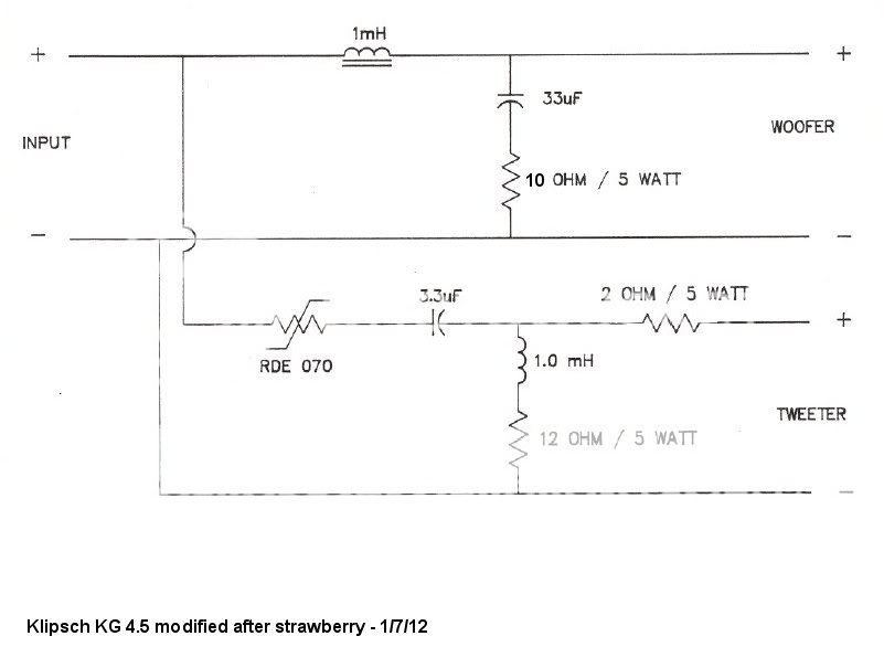
Yeah, and you can add the 2.2 uF in parallel with the 3.3 uF to get 5.5 uF for the tweeter if you find the mids being mute. The 12 ohm with the tweeter should be removed. I don't know what the RDE 070 is. Variable resistor? If so the 2 ohm on the tweeter is not needed. But try with the 2 ohm first. If you have a 0.5 mH inductor for the woofer, try that. A 1.0 mH inductor will mute the woofer quite a bit. With a 1.0 mH inductor you will need a 5.5 uF for the tweeter.
Last edited:
The plus for the woofer should go to minus on the tweeter. When you have found the right capacitor value for the tweeter, buy a polyester or polypropylene capacitor instead. You should put a small 0.33 uF, or so, capacitor in parallel to the tweeter capacitor for improved sound resolution. The biggest capacitor you should put on the tweeter is 10 uF, should the mids really be missing with your 1.0 mH inductor for the woofer.
Last edited:
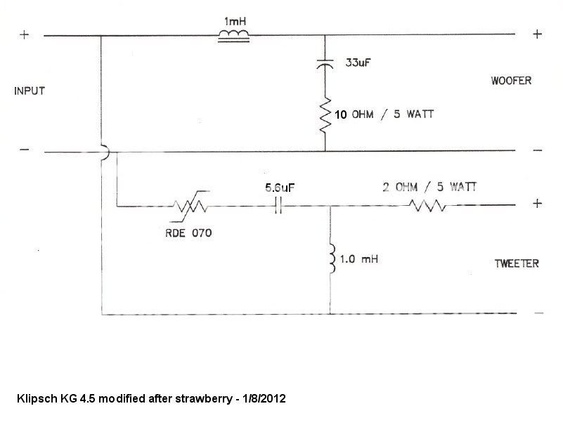
That looks fine. For the tweeter, listen to capacitors 4.7 to 10 uF and see what sounds the most natural. Also, put a small, 0.33 uF or so, polyester capacitor in parallel with the electrolyte capacitor for the woofer. It will vastly improve sound resolution for the woofer.
Based on some creative guesswork I'm concerned about these changes. Firstly that they might cause a considerable increase in tweeter output, possibly more than 12dB below the current crossover frequency. Secondly, the the output of the woofer may increase above the current crossover frequency exposing more breakup issues, not less.
How can you design a crossover without knowing the drivers response?
yeah, ofcourse you can

with or without FR response...all depends of what you expect of it
just dont claim it will be perfect
theres always something to learn
but most lesson learned also comes at a price
and even experts fails, sometimes
thats part of the 'DIY-game
I'm confused about something.
In the unmodified KG4.5 schematic (post #10 in this thread), on the woofer lo-pass filter... The 2 ohm resistor in series with 33uF cap across the woofer -- That's not a zobel, is it? I've been looking at other sites' descriptions of designing a crossover, and it seems fairly common to put a low value resistor in series with the parallel cap of a 2nd order LP filter to alter the action of the filter.
Zobel networks are impedance altering filters, and in order for that to be the case in this filter, wouldn't the resistor's value need to be more like 9 or 10 ohms, to make a difference over the Re of the driver?
Are we sure the LP filter on the KG4.5 is not a 2nd order filter with an added resistor?
Or is it really a 1st order LP filter with a weird Zobel on the woofer? In that case, what's with the weird values chosen for this Zobel?
Like I said, I'm confused.
________________________________________
What led me to that question is that in the original schematic, the HF horn is not reversed polarity with the woofer. With a 2nd order filter, normally the tweeter would be polarity reversed to the woofer. But that is not the case here.
--
Last edited:
- Status
- This old topic is closed. If you want to reopen this topic, contact a moderator using the "Report Post" button.
- Home
- Loudspeakers
- Multi-Way
- Taming harshness in horn tweeter