
OK so lets do this by elimination.
Unsolder the wires from one of the RCA's
Just one channel will do.
temporarily clip the input to the wire leading to the cap on that channel, and clip the ground on.
Use your i-pod as the volume control.
If nothing happens then we know it's not the pot or the RCA connections shorting anything out.
Unsolder the wires from one of the RCA's
Just one channel will do.
temporarily clip the input to the wire leading to the cap on that channel, and clip the ground on.
Use your i-pod as the volume control.
If nothing happens then we know it's not the pot or the RCA connections shorting anything out.
audio1st said:Hello again
it seems that your speaker - v'se are not connected
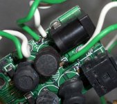
Good point, have you got a picture of the whole amps output stage?
stephanko said:Hello Lostcause: I will do, might not happen 'til tomorrow
Hello audio1st: Not sure what a v'se is..? Please enlighten me
it should have been - ve, negative..
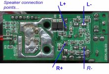
resistance from input to output should be the same at all speaker terminals..
- sorry, still don't understand the 've' thing.
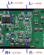
- Re-checked (if I understood you correctly) resistance between RCA+ and speaker+ and speaker-
to speaker+: 53k
to speaker-: infinity
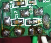
- here is a picture of one speaker soldering as well as the power in soldering.
- Re-checked (if I understood you correctly) resistance between RCA+ and speaker+ and speaker-
to speaker+: 53k
to speaker-: infinity
- here is a picture of one speaker soldering as well as the power in soldering.
Attachments
audio1st:
see the picture for results..... so no wonder I have no output signal, correct? I should probably try to connect the negative side of the speaker to the points labeled L- or R- on your picture?
Question: As I was pondering this.... I realized I only soldered the speaker wires on the bottom of the PCB. Could this be the reason for not having any continuity? Should I try to solder them on the top side of the PCB as well?
Attachments
stephanko said:Question: As I was pondering this.... I realized I only soldered the speaker wires on the bottom of the PCB. Could this be the reason for not having any continuity? Should I try to solder them on the top side of the PCB as well?
Yup, if you look closely at your board you'll see that the - is only connected on the top part of the board and + is only connected on the bottom side for the R connectors. And both only on the top side the L connectors but I guess you just lucky getting the plus one to work. I assume you soldered the plusses first.
so it holds true one more time..... if you assume you make an *** out of U and ME. My (false) assumption was that the the top and bottom side of the PCB (looking at a single hole) are contacted through...
I will heat up the iron....... and keep you posted (hopefully with good news)
Thanks!
I will heat up the iron....... and keep you posted (hopefully with good news)
Thanks!
- Status
- This old topic is closed. If you want to reopen this topic, contact a moderator using the "Report Post" button.
- Home
- Amplifiers
- Class D
- t-amp stealth mod problem - no sound output at all...