Yes, it helps! A lot  . I always appreciate comments, thoughts etc, especially if they contribute to anything I'm building.
Building without sims . I wouldn't even try.
I can move the ports about 2 cm towards the throat if I construct the horn like this:
The mids seem a bit 'disoriented', but this allows for the closest-to-mouth mounting. And since the distance from port to center of the cone is the same with every unit, I figure it doesn't matter to the sound.
And yes, I started a second prototype. This time I'll do my best to build it properly. Perhaps it's even going to end up as a final version, at least I hope so .
.
The throat needs to be truncated at about 2.2 cm from the apex, but this way I am sure the horn has no 'astigmatism'.
. I always appreciate comments, thoughts etc, especially if they contribute to anything I'm building.Building without sims
. I wouldn't even try.I'm not sure I understand what you mean. Why would adding ports increase the port to tweeter distance?Looking at the positioning of the ports on your horn the drop from 800hz rolloff to 700hz from adding the extra mids is along the lines of what I would expect, it's simply down to slight increases in port to tweeter distance (at least that's my view)
I can move the ports about 2 cm towards the throat if I construct the horn like this:
An externally hosted image should be here but it was not working when we last tested it.
An externally hosted image should be here but it was not working when we last tested it.
An externally hosted image should be here but it was not working when we last tested it.
An externally hosted image should be here but it was not working when we last tested it.
The mids seem a bit 'disoriented', but this allows for the closest-to-mouth mounting. And since the distance from port to center of the cone is the same with every unit, I figure it doesn't matter to the sound.
And yes, I started a second prototype. This time I'll do my best to build it properly. Perhaps it's even going to end up as a final version, at least I hope so
.The throat needs to be truncated at about 2.2 cm from the apex, but this way I am sure the horn has no 'astigmatism'.
I'm not sure I understand what you mean. Why would adding ports increase the port to tweeter distance?
It's not about adding ports but about where the ports are added, if they are all put in the same lateral position down the horn then when you measure you should find a marginally greater distance from the tweeter to the ports on the wider angled wall compared with the others (which can only lower potential hf response). At least that is what I have always found.
I also have a thought on asymmetrical port layout, but that is completely unsubstantiated at present.
You're not hanging around are you, that is an interesting arrangement! I'll be curious to see where you position the woofers.
2cm closer should definitely get you close to the 1000hz area.
Btw I mean't to say I did like your idea of having the mid under the woofer (it's not something I would've thought of to be honest) but it's given me a couple of ideas about the possibility of making an ultra compact horn if I get the time.
Cheers Paul.
Ah, thanks. Now I understand...if they are all put in the same lateral position down the horn then when you measure you should find a marginally greater distance from the tweeter to the ports on the wider angled wall compared with the others (which can only lower potential hf response).
 . So it's the shortest distance that's important, not lateral position. Makes a lot of sense, come to think of it. It's all about wavelength, isn't it
  .
.Not when I'm eager to get something doneYou're not hanging around are you, that is an interesting arrangement! I'll be curious to see where you position the woofers.
2cm closer should definitely get you close to the 1000hz area.
. I plan to position the woofers at about the same place I did with the first prototype, at the mouth end a little closer to the horn so the magnets don't extend so much, perhaps even a little higher up towards the throat. There will be a (small) front chamber where the side mid resides, just as with the first proto.ThanksBtw I mean't to say I did like your idea of having the mid under the woofer (it's not something I would've thought of to be honest) but it's given me a couple of ideas about the possibility of making an ultra compact horn if I get the time.
 . It's just how it worked out.
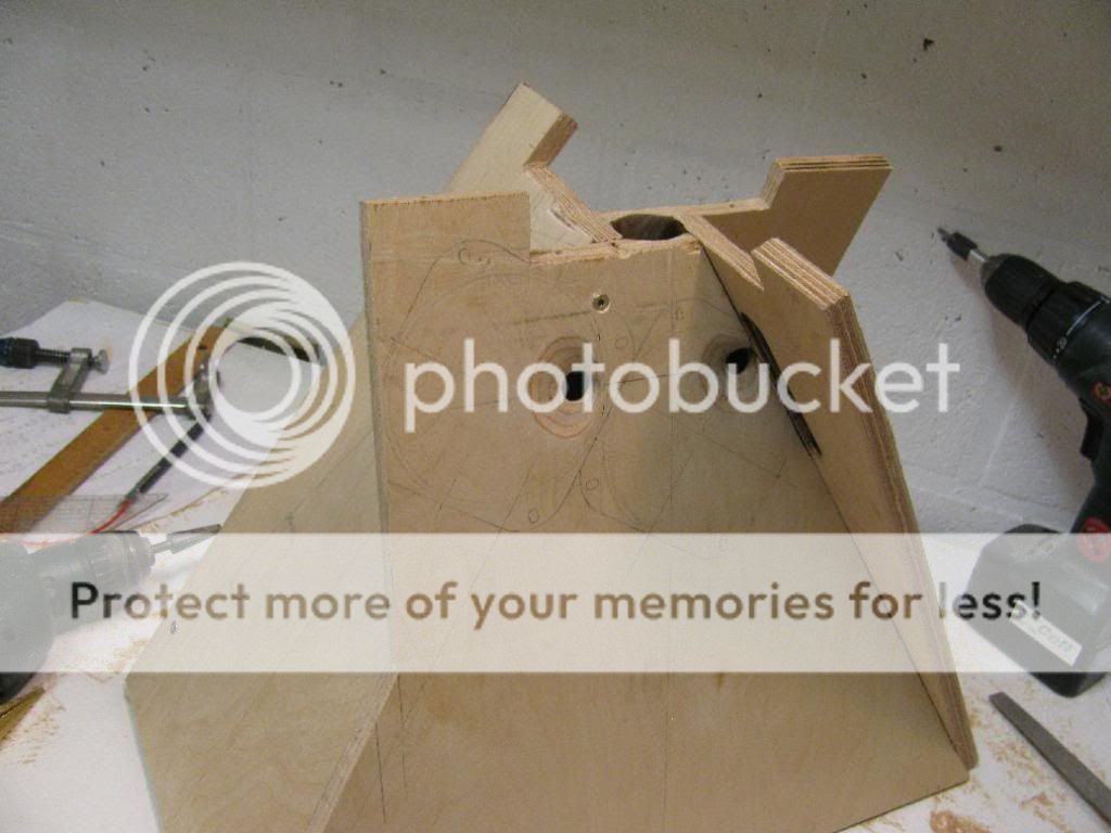
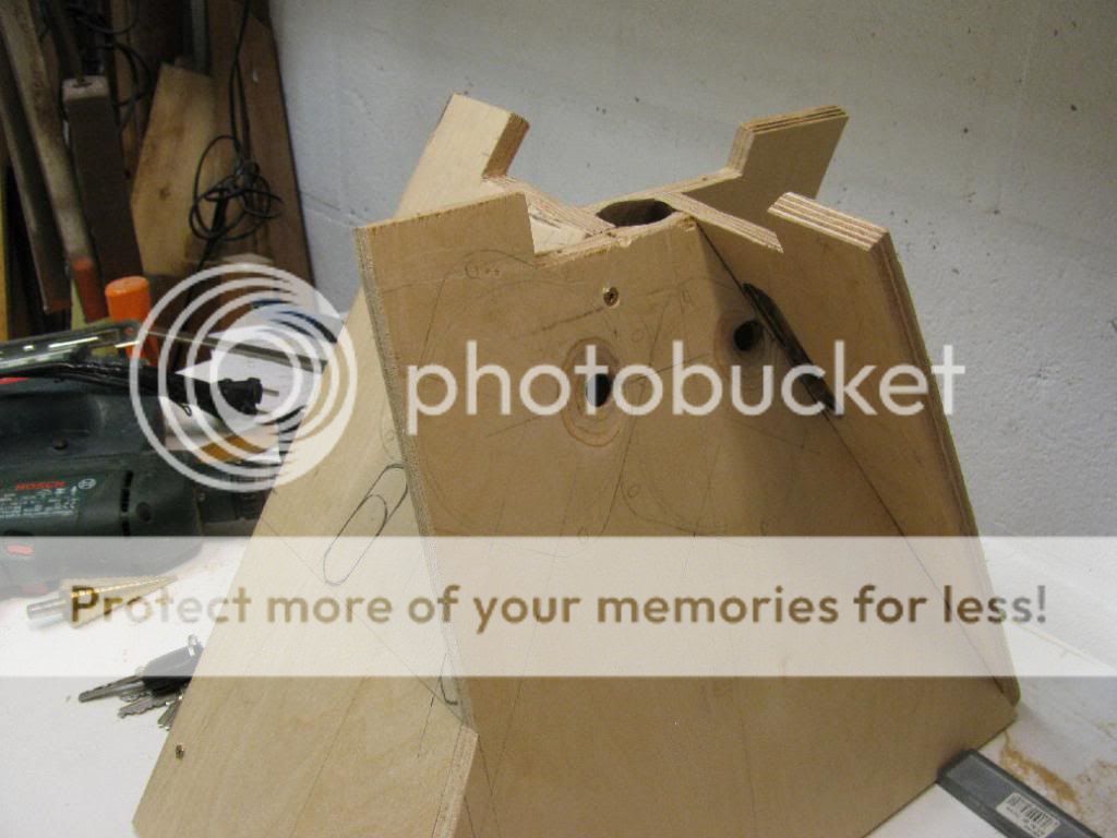
Some progress from this weekend. Most pictures are self-explanatory .


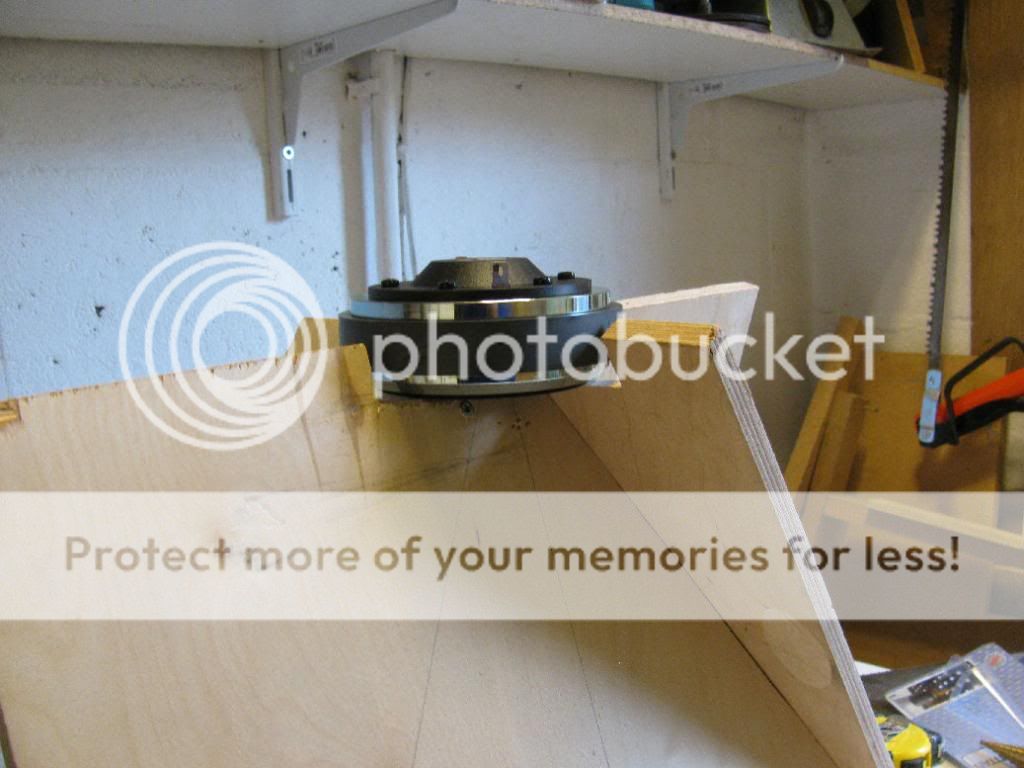


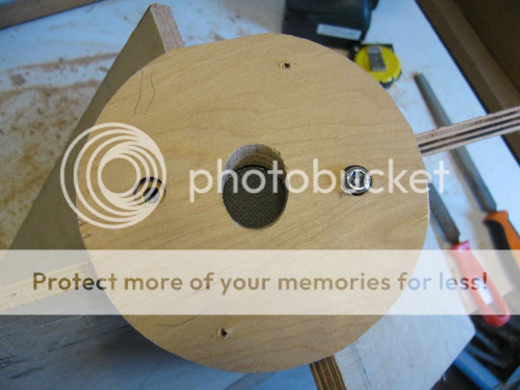


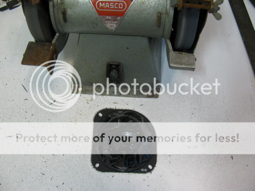
Better cover the magnet when you do this.


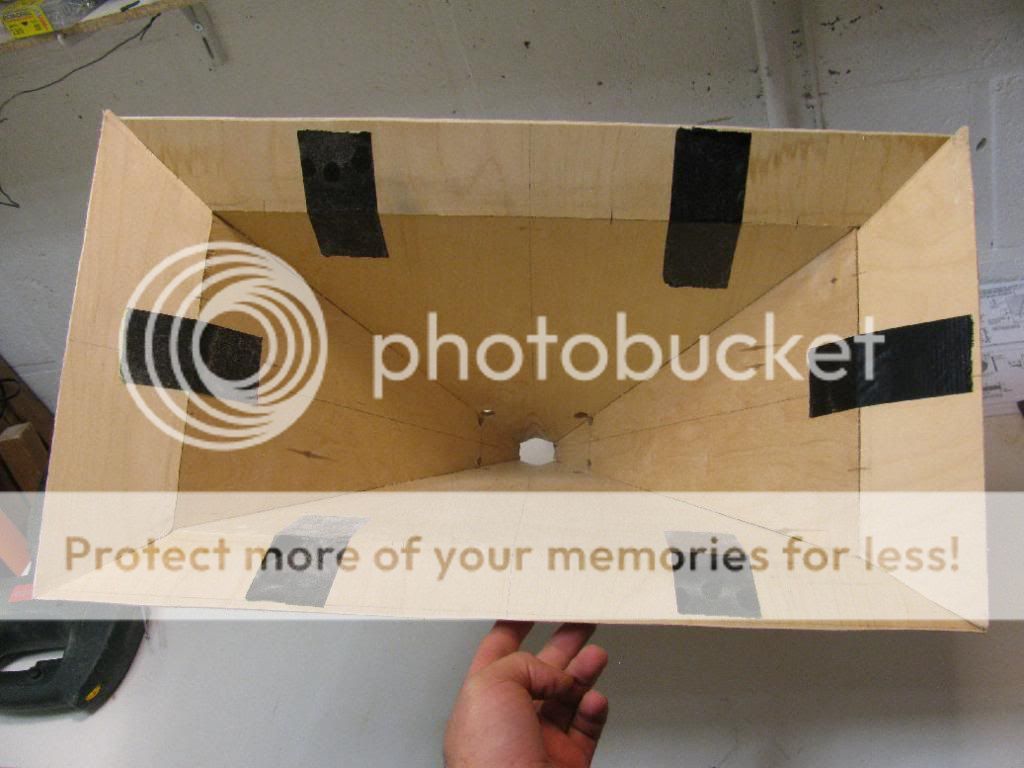
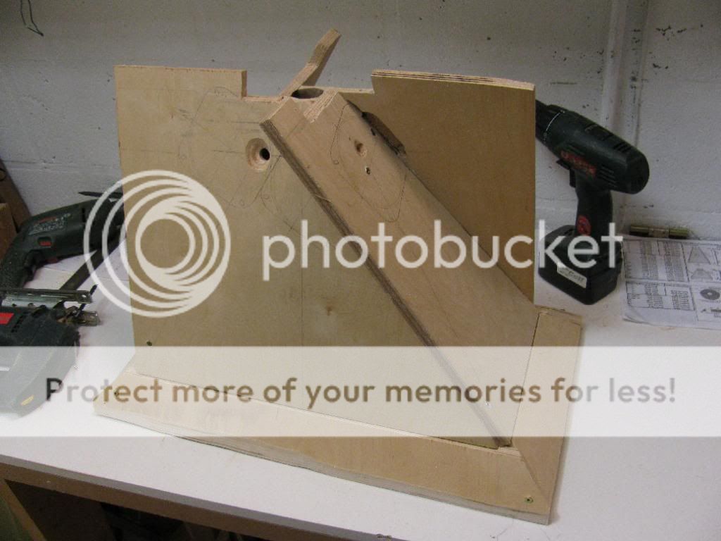

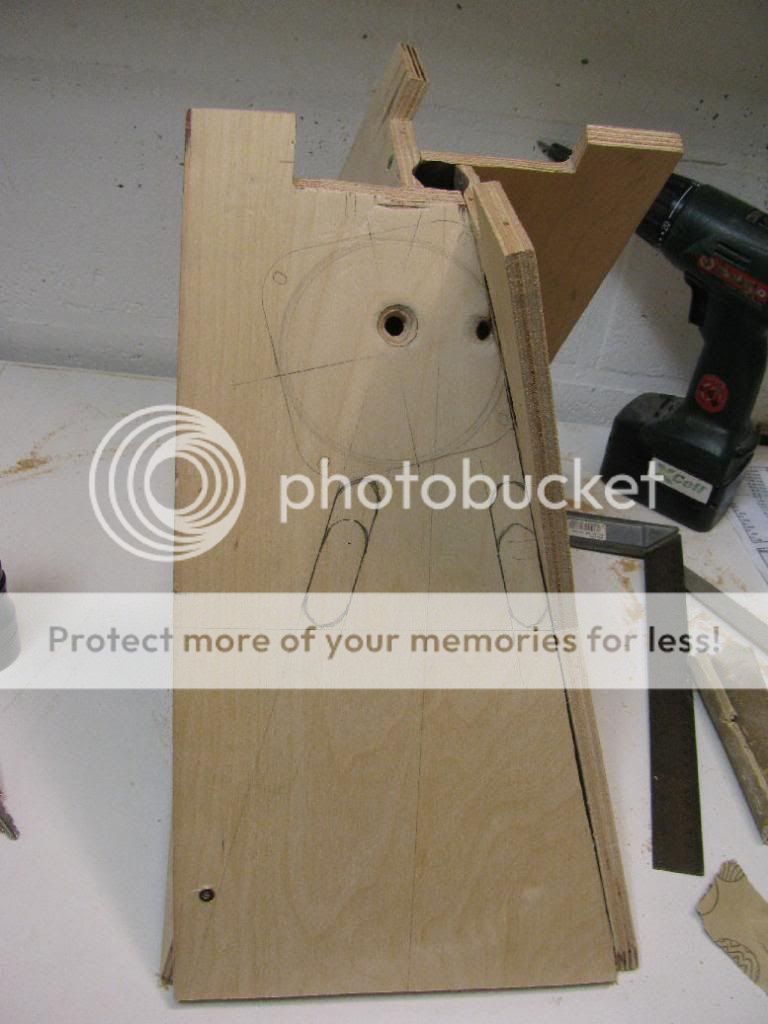
The woofers are going to be mounted on a baffle that goes on the side, just like I did with my first prototype. I wonder though if I get away with the woofer ports... Perhaps they're too far towards the throat??. I plan to make them 2x7 cm (.79" x 2.75"), like I drew in the second last photo. But that still is a bit small, I would like to make them a little bigger. But I wonder if I could make them wider or round without too much impact on the horn/frequency curve of the mids and HF unit...
.


Better cover the magnet when you do this
.


The woofers are going to be mounted on a baffle that goes on the side, just like I did with my first prototype. I wonder though if I get away with the woofer ports... Perhaps they're too far towards the throat??
. I plan to make them 2x7 cm (.79" x 2.75"), like I drew in the second last photo. But that still is a bit small, I would like to make them a little bigger. But I wonder if I could make them wider or round without too much impact on the horn/frequency curve of the mids and HF unit...Some progress from this weekend. Most pictures are self-explanatory
wow...
thank you for very detail pictures.
Thijs666,
Nice work on second prototype - are you using any simulations to guide your hole placements and size for the mids and bass? That is really critical otherwise you are really not going to optimize the locations of the bandpass. I like your arrangement for squeezing drivers close together.
Nice work on second prototype - are you using any simulations to guide your hole placements and size for the mids and bass? That is really critical otherwise you are really not going to optimize the locations of the bandpass. I like your arrangement for squeezing drivers close together.
I'm not sure if I'll run into phase issues with those side-mids. The distance from the center of the membrane to the ports is not the same for both port wholes...
With the other four mids the relative port position is the same among the four of them.
This shouldn't really matter. Sound doesn't originate from a single point on the cone. The entire volume under the cone gets pressurized so the relative port location under the cone doesn't really matter.
Thijs666,
Nice work on second prototype - are you using any simulations to guide your hole placements and size for the mids and bass? That is really critical otherwise you are really not going to optimize the locations of the bandpass. I like your arrangement for squeezing drivers close together.
Thanks! Well, for the position of the mid ports I used the Hornresp simulations I posted higher up this thread. For the size I tried to use Hornresp as well, but altering the port area didn't seem to influence the particle velocity much, or even at all
. So I figured I could start with a smaller diameter and see how it measures. If it doesn't work out, I can always make them bigger.As for the woofer part, I did try to simulate the horn part in Hornresp, and it gave me a very nice 100-300Hz curve, just like I wanted (also posted higher up this thread), but measurements proved this simulation to be way off (I reported my measurements here as well). I did try to simulate a 4th order band pass in WinISD, but nothing very useful came out. Sadly my Akabak skills are non existent, so that's no option either...
Perhaps I can use WinISD to determine the port size.
Thanks! I think I read about this somewhere in a forum during my 'research frenzy', but I couldn't recall where so I couldn't find itThis shouldn't really matter. Sound doesn't originate from a single point on the cone. The entire volume under the cone gets pressurized so the relative port location under the cone doesn't really matter.
.I'm not sure if I'll run into phase issues with those side-mids. The distance from the center of the membrane to the ports is not the same for both port wholes...
With the other four mids the relative port position is the same among the four of them.
Is there a reason why you are using 1 hole per driver for the two pairs of mids, but using 2 holes per driver for the single mids on the sides?
Do you have a plan yet how the woofers are going to fit onto this new design? the mids and their mounting boards seem to take up quite a lot of space, I don't see where two 12"s will go without making the box larger.
Great thread by the way, I love your detailed pictures.
Yes, there is! The ports need to be entering the horn in a corner to be as unobtrusive to the HF part as possible. There are only four cornersIs there a reason why you are using 1 hole per driver for the two pairs of mids, but using 2 holes per driver for the single mids on the sides?
. For the sake of symmetry the side mids have two ports which are smaller, but together they are similar in size as one 'big' port.Yes, I do. You'll seeDo you have a plan yet how the woofers are going to fit onto this new design? the mids and their mounting boards seem to take up quite a lot of space, I don't see where two 12"s will go without making the box larger.
.Thanks! You're welcome. I do benefit from the knowledge that's up for grabs here for free, so it's the least I can doGreat thread by the way, I love your detailed pictures.
woofer choice
Hi Thijs,
Very interesting design and build. I'm in the proces of designing a portable PA, using tapped horns with Faital speakers.
ever considered 4 8 inch speaker versus 2 12 inch.
Faital has some nice 8 inch at low cost and weight. I'm building a bass guitar stack with 8 Faital 8FE200 in 4 cabinets of 25 * 50 * 45 bass reflex cabinets. They sound very nice and punchy.
Candidate for your horn.
kind regards,
Frans Wessels
Yes, I did.Ever considered 4 8 inch speaker versus 2 12 inch.
Faital has some nice 8 inch at low cost and weight. I'm building a bass guitar stack with 8 Faital 8FE200 in 4 cabinets of 25 * 50 * 45 bass reflex cabinets. They sound very nice and punchy.
Faital 8FE200: 4*49,50 euros = 200 euros, Vd = 0.467cm*191cm^2 * 4 = 356.788 cc, P = 4*130W = 520W
Eminence Beta12A-2: 2*72 euros = 150 euros, Vd = 2*237cc = 474 cc, P = 2* 250W = 500W.
So take your pick
.I'd probably pick the 8", which would not require the mid drivers that are giving you such a PITA.Yes, I did.
Faital 8FE200: 4*49,50 euros = 200 euros, Vd = 0.467cm*191cm^2 * 4 = 356.788 cc, P = 4*130W = 520W
Eminence Beta12A-2: 2*72 euros = 150 euros, Vd = 2*237cc = 474 cc, P = 2* 250W = 500W.
So take your pick
But I'm prejudiced since I use (Eminence Alpha) 8" in my PA
.8 inch
Thijs,
Maybe 2x 8 inch since you are using the "woofers" as mid bass, they most likely can handle the punishment.
So 2x 8 inch, (optional 4 x 4 inch) and a high unit.
I think the 8 inch are in your advantage also because you want the horns not to grow big.
Just a thought.
kind regards,
Frans Wessels
I suspect that your midrange woes have to do with the M10 driver. Here are some of my measurements on a 90x45 degree horn. The mid is ported into the horn wall at about 2.5" (need to double check that) from the 1" compression driver entrance hole. The port hole is 1/2" through 1/2" plywood. The red trace is the Misco JC5RTF. The blue trace is the Visaton M10. The big notch at appears to be caused by cone flex. Those who have seen the M10 in person can see that the cone is very flat which means that it tends to flex much easier than a cone with more angle.

In an effort to fix the problem I did some experimenting. The red trace is an M10 driver with one coat of shellac applied to the cone. That yielded very little change. So I glued a mesh layer to the cone with more shellac and saw some change.

In an effort to fix the problem I did some experimenting. The red trace is an M10 driver with one coat of shellac applied to the cone. That yielded very little change. So I glued a mesh layer to the cone with more shellac and saw some change.
I have to agree. Every driver Ive simmed seems to have a somewhat better top end than the M10, not that Im an expert but there does seem to be better options out there.
Well I'm not sure the M10 is a lost cause… if you modify it. Here's a comparison of the Misco vs the Modified M10 with the mesh screen shellacked on the cone. The sensitivity is not the same but if you adjust for it, the M10 does reach a pinch higher than the 5" Misco. It should be noted that the cone area of the M10 is about the same as the Misco even though it is a much smaller driver over all. The very narrow gasket border around the edge and minimal surround means you can get it in pretty tight to a compression driver. And I don't know that my modification is the best one that can be done. A fiberglass/epoxy treatment might yield better results. And lastly, remember that my measurements are from a test horn with one 1/2" hole and no frustum. I would expect the lowpass to bump up a bit with a larger hole and some hollowing out on the backside.
Misco is purple, Visaton is Green.

And before and after:

I thought with the temporary absence of Thijis666 I would have a go at answering a few of the comments on here.
With regard to using four 8 inch woofers without the mids while in theory this sounds perfectly plausible, however in practice you would find it hard to fit four 8" woofers close enough to get you near to the 1000hz crossover that the op is aiming for.
Not to mention that situating suitable sized ports for four 8" woofers that far up the horn towards the tweeter would mean very little horn wall would be left (unless using a particularly wide angle horn), meaning the tweeter response would probably suffer to quite an extent.
With regard to using two 8 inch woofers, this is a method I have used myself and it can be implemented without too much difficulty, however this arrangement will not provide the 130db level capability that the op is looking for (unless crossed over at an unusually high level). So not really a viable option, unless there is some super duper long throw 8" woofers I don't know about.
Now to the Visaton M10, this is a driver I know pretty well.
It is certainly not a driver that I have ever felt had any inherent problems at the top of it's operating band on a horn. Quite the opposite! If I was going for extended hf response from a mid on a horn it is one of the drive units I would choose for my short list.
The one area I am not so keen on it is that it's low frequency extension doesn't extend very deep down and before it rolls off it has a bit of a hump in it's response, which makes me want to roll it off earlier to tame this bump. Not a problem if addressed in the design stage though.
I wonder if the low opinion of this driver mentioned above is down to mis-application rather than any shortcoming of the driver itself.
I only mention this because the use of a single 1/2" hole for a 4" driver unit seems unnaturally small to me. I've measured the driver and a 1/2" hole represents a compression ratio of 52 to 1.
Under these circumstances I'm not surprised the driver might struggle and I would expect it to.
I always aim for a more standard ratio of around 10 to 1 and have not had any problems, nor felt any need to strengthen the cone.
I hope this helps,
Paul.
Last edited:
The 1/2" hole is definitely small. I simply used it as a starting point (easier to make a small hole bigger than a big hole smaller) to compare midrange drivers. The 5" Misco was my reference and since it's response was so flat to begin with I didn't consider the hole size to be a problem. Again, I was merely looking for difference between drivers, not looking for a specific response on that particular horn. The Visaton driver had a big dip at 1Khz whereas the Misco had a very different character at that frequency. But it's clear that the Visaton had more output up higher than the Misco. I do suspect that the dip could be smaller with a weaker load on the cone but it seemed tragic enough to me to try to do something about it. 2 coats of shellac moved the dip up a little bit. Adding reinforcement (and weight) to the cone moved it up a lot further.
- Status
- This old topic is closed. If you want to reopen this topic, contact a moderator using the "Report Post" button.
- Home
- Loudspeakers
- Multi-Way
- Synergy with BMS 4550, Visaton M10 and ...