Try the cheap 6.5 in polycone buyout driver from PE for the woofer - it sims well and has nice flat response with bass down to 50 Hz (sealed box) and reach up to 1 kHz. You can have a two way. The drivers are less than $5 ea and qnty 4 will get you to 89 to 91 dB efficiency.
http://www.diyaudio.com/forums/multi-way/244890-synergy-horns-dayton-prv-5.html#post3687739
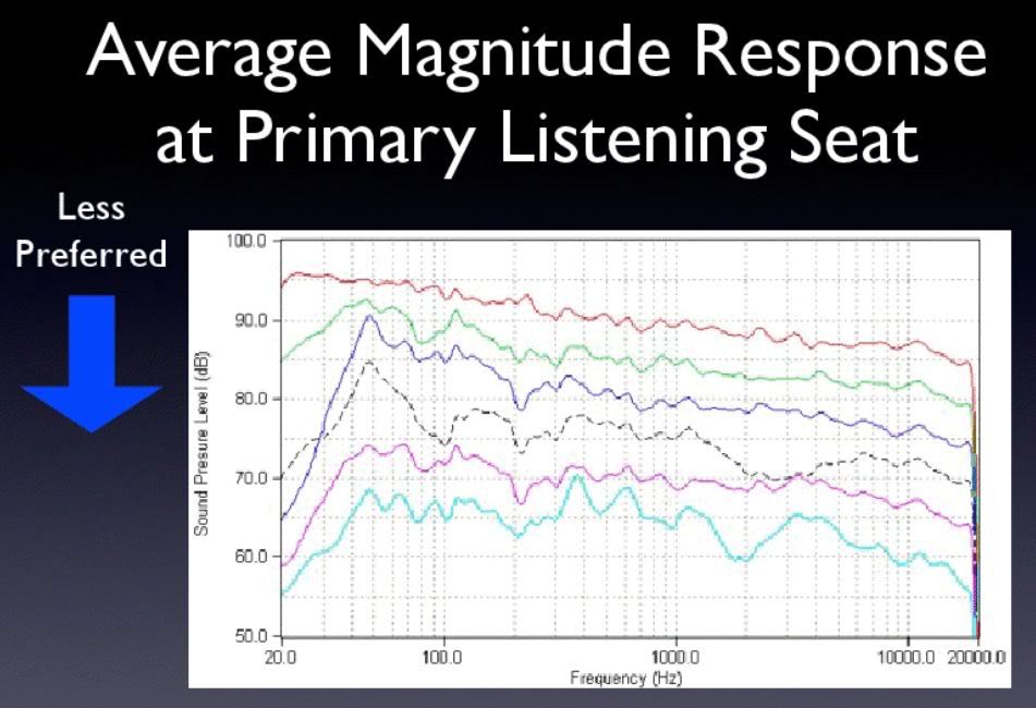
Efficiency bandwidth product rears its ugly head again. It’s just an opinion, but I feel like too much sensitivity is being traded away for only an additional 50Hz on the bottom end. By the time you get a pleasing downward power response the high frequencies will be down around 79 dB to 81dB at 1W/1M.
Which was why I was pushing for 8 (cheap) drivers initially to get 94 dB efficiency - which may still be doable if the hole/slots are located far out enough away from the throat.
That would be interesting if you could get it to work. It would open up additional options.
Thanks guys  .
.
@Art/weltersys:
I bet he didn't have a tapped horn drum riser sub.
There's a nasty spike @500Hz with the Beta's, but it seems to be related to Vtc (front chamber value). With 10000cc, it's almost gone in the Loudspeaker wizard. I hope it's a glitch or something. I think I'll go ahead and order 2 Beta's...
I don't really have a suitable space to measure the sub. My intention was to measure the whole set at my mom's when it's finished and dial it all in properly. She lives in the countryside and has a little more space than I do... But these Synergy horns took a lot of time to wrap my head around...
@xrk:
Thanks for your suggestion. But I'm in Europe/The Netherlands... Shipping costs, import taxes, not funny.
And I doubt if those are going to be able to 130dB.
In the mean time, this afternoon I installed the last two M10's, so now I have 6 of them firing in the horn. Here's the frequency response:
This is measured at 40cm (~15 inch) in front of the horn, on axis. No reference to 1W/m, just at a bearable level. Both upper graphs are with 5dB more gain.
The two extra mids flatten out the response very nicely! Though they fall of a little early. I'm not sure what I can do about this . Again, if you feel you can enlighten me... .
I had to modify the side-M10's a bit to make them fit...
.@Art/weltersys:
I bet he didn't have a tapped horn drum riser sub
. There's a nasty spike @500Hz with the Beta's, but it seems to be related to Vtc (front chamber value). With 10000cc, it's almost gone in the Loudspeaker wizard. I hope it's a glitch or something. I think I'll go ahead and order 2 Beta's...
I don't really have a suitable space to measure the sub. My intention was to measure the whole set at my mom's when it's finished and dial it all in properly. She lives in the countryside and has a little more space than I do... But these Synergy horns took a lot of time to wrap my head around
...@xrk:
Thanks for your suggestion. But I'm in Europe/The Netherlands... Shipping costs, import taxes, not funny
.And I doubt if those are going to be able to 130dB
.In the mean time, this afternoon I installed the last two M10's, so now I have 6 of them firing in the horn. Here's the frequency response:
An externally hosted image should be here but it was not working when we last tested it.
This is measured at 40cm (~15 inch) in front of the horn, on axis. No reference to 1W/m, just at a bearable level
. Both upper graphs are with 5dB more gain.The two extra mids flatten out the response very nicely! Though they fall of a little early
. I'm not sure what I can do about this . Again, if you feel you can enlighten me... .I had to modify the side-M10's a bit to make them fit...
An externally hosted image should be here but it was not working when we last tested it.
I think I know where I went wrong. Con12 was too short in the sims . Here's something that's more correct:
Here the SPL simulation resembles the measured curve more.
And now for the solution. If I drill the port holes not at a right angle through the side, but a little 'upwards', I should be able to get the port 1 cm closer to the apex of the horn. I also haven't made frustrums yet, but looking at the sims below, I really should.
. Here's something that's more correct:An externally hosted image should be here but it was not working when we last tested it.
An externally hosted image should be here but it was not working when we last tested it.
Here the SPL simulation resembles the measured curve more.
And now for the solution. If I drill the port holes not at a right angle through the side, but a little 'upwards', I should be able to get the port 1 cm closer to the apex of the horn. I also haven't made frustrums yet, but looking at the sims below, I really should
.An externally hosted image should be here but it was not working when we last tested it.
An externally hosted image should be here but it was not working when we last tested it.
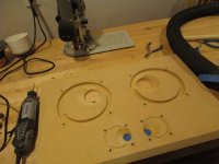
Some more pics of my first proto. I know you like them .
I made the frustrums.
Here's how tight it gets for the side-M10s.
Here you see where the mids tap into the horn.
Here's the whole thing again.
.I made the frustrums.
An externally hosted image should be here but it was not working when we last tested it.
Here's how tight it gets for the side-M10s.
An externally hosted image should be here but it was not working when we last tested it.
An externally hosted image should be here but it was not working when we last tested it.
Here you see where the mids tap into the horn.
An externally hosted image should be here but it was not working when we last tested it.
Here's the whole thing again.
An externally hosted image should be here but it was not working when we last tested it.
Here's the new frequency response after adding frustrums. All relative measurements, not even close to 1 watt or 2.83 volts. I can't do that where I'm measuring right now (the living room ). O well, I already know they'll be frikkin' loud.
I'm not sure what happened, but I think in my previous measurements the mids were much less efficient. Perhaps a loose connection. Anyway, adding the frustrums didn't bring much high end extension of the mids. A reasonable crossover frequency seems 800Hz. I would love to have it a little higher, at 1000Hz, to spare the compression driver a little when playing at full power...
But what's up with that big 5dB dip at 2.8kHz? I have to move the mic around to see if it's not a measurement quirk or reflection or whatever.
And here's the frequency and phase response after dialing in the filters and EQ.
I was able to get rid of that 5dB dip with some EQ, but it isn't real nice. I'd rather fix it at the origin...
Listening to this box after dialing it in is already pleasing. Even without everything below 300Hz! Vocals are just excellent . Amazing coherence and detail. I have high hopes for a stereo pair + woofers and sub
). O well, I already know they'll be frikkin' loud.An externally hosted image should be here but it was not working when we last tested it.
I'm not sure what happened, but I think in my previous measurements the mids were much less efficient. Perhaps a loose connection
. Anyway, adding the frustrums didn't bring much high end extension of the mids. A reasonable crossover frequency seems 800Hz. I would love to have it a little higher, at 1000Hz, to spare the compression driver a little when playing at full power...But what's up with that big 5dB dip at 2.8kHz? I have to move the mic around to see if it's not a measurement quirk or reflection or whatever.
And here's the frequency and phase response after dialing in the filters and EQ.
An externally hosted image should be here but it was not working when we last tested it.
I was able to get rid of that 5dB dip with some EQ, but it isn't real nice. I'd rather fix it at the origin...
Listening to this box after dialing it in is already pleasing
. Even without everything below 300Hz! Vocals are just excellent . Amazing coherence and detail. I have high hopes for a stereo pair + woofers and sub Perhaps a loose connection
Try being even more aggressive with those frustrums...or putting slightly larger holes in place.
This is what I ended up with on mine...and I have 3" mids with .875" ports. I cut them back until there was about 1/8" of material at the exit. I had to make them asymmetrical to get the mids to fit...
Scott
Attachments
since it is proto tests, why not design it so that you can change the hole
would not be difficult making that part 'detachable'
thougth it might make the hole placement less than optimal, but whatever
I tried that...but I ended up finding it easier to just keep modifying a test horn until it was unusable and then....build it again.
It got to the point where I had them filled and re-drilled enough with putty I was putting putty on putty hoping it would stick.
Scott
Just the Behringer DCX2496The response curve looks fantastic. What are you using to effect the EQ and XO functions?
. Take a close look at the combined graph (with the yellow/gold curves) and you'll see the XO parameters in the box on the left. I used about 6 parametric EQs on the compression driver and just one on the mids...Thanks. The M10s are, well, 10cm, (or 4") in diameter and my tap holes are 2.2cm, or .875", the same as yours. I fear if I make them any bigger, they'll interfere with the HF response of the compression driver, as there will be hardly any horn wall left, see pic from the inside of the horn with the tap holes showing.Try being even more aggressive with those frustrums...or putting slightly larger holes in place.
This is what I ended up with on mine...and I have 3" mids with .875" ports. I cut them back until there was about 1/8" of material at the exit. I had to make them asymmetrical to get the mids to fit...
Scott
But since this is a proto, I can and probably will try.
Did it work with your prototypes? Have you measured with and without frustrums and did you notice any difference?
I'm afraid that it would. The white lines you see on the photo below is actually the kit that's closing the gaps between the mids that are on the sides... Your suggestion had already crossed my mind, but thanks anywaywould not be difficult making that part 'detachable'
.An externally hosted image should be here but it was not working when we last tested it.
The relationship of enclosed space in front of the driver to port dimension and port depth create an acoustical bandpass.How do you determine the size of the ports for the mids? Ive simmed a horn and just copied your specs but dont really understand how to optimise them for my mids.
If the port is too large, the driver will roll off at a lower frequency than may be desired, too small, and the driver has a large upper peak followed by a steep drop off and more peaks.
Hornresp will show you the basic response when changing the relationships between enclosed space in front of the driver to port dimension and port depth, but does not consider driver breakup in the upper end of the response, experimentation must be done to determine the actual response.
Maybe this will help:Thanks weltersys. That part I understand, what Im missing is which tabs in hornresp are responsible for those changes?
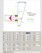
Hornresp for Dum... hmm... Everyone
- Home Theater Forum and Systems - HomeTheaterShack.comVrc (volume of Rear Chamber), Lrc (length rc), Vtc (volume Throat Chamber, the enclosed space in front of the driver), Atc (area tc), Lpt (Length of Port), Ap (Area of Port) and S2 placement all affect the response as I described.Thanks weltersys. That part I understand, what Im missing is which tabs in hornresp are responsible for those changes?
In a real offset horn, the Vtc and Lpt/Ap may be combined in a single conical chamber, and results need to be worked out empirically.
Attachments
- Status
- This old topic is closed. If you want to reopen this topic, contact a moderator using the "Report Post" button.
- Home
- Loudspeakers
- Multi-Way
- Synergy with BMS 4550, Visaton M10 and ...