Ok, I made some progress again. Here are some pics of how I put the woofers in:
The idea is to put baffles on the sides of the horn and create some sort of front chamber.
They can't go on the top and bottom, they'd be adding about 9 cm on each side, which would add up to 18+35=53cm, which is too wide to fit in the sub.
Here's how the baffle looks like after it's installed.
The side-mids are still accessible after removing the woofer.
Woofers mounted.
...And in a box.
It sure isn't the nicest box I've ever seen , but at least it works. More on that in my next submission...
The idea is to put baffles on the sides of the horn and create some sort of front chamber.
An externally hosted image should be here but it was not working when we last tested it.
An externally hosted image should be here but it was not working when we last tested it.
An externally hosted image should be here but it was not working when we last tested it.
An externally hosted image should be here but it was not working when we last tested it.
They can't go on the top and bottom, they'd be adding about 9 cm on each side, which would add up to 18+35=53cm, which is too wide to fit in the sub.
An externally hosted image should be here but it was not working when we last tested it.
Here's how the baffle looks like after it's installed.
An externally hosted image should be here but it was not working when we last tested it.
The side-mids are still accessible after removing the woofer.
An externally hosted image should be here but it was not working when we last tested it.
Woofers mounted.
An externally hosted image should be here but it was not working when we last tested it.
An externally hosted image should be here but it was not working when we last tested it.
...And in a box.
An externally hosted image should be here but it was not working when we last tested it.
It sure isn't the nicest box I've ever seen
, but at least it works. More on that in my next submission...Nice way to integrate the woofers into a plenum that contains the mids. This will give you the added benefit of a large volume to provide a natural acoustic low pass for the woofer output. Your two woofer ports seem awfully small in cross section - did that area work well in the sims? I found that having a small bass injection port causes a peak at the high end of the bass response. Great work, so what it doesn't look pretty - this is how prototypes are made. How do you access the mid driver buried underneath the panel now?
Yeah, they were too small. I made a new, bigger (longer) set more towards the throat, about 19cm from the throat, instead of 30cm you see in the picture, seemed ok, surface area-wise. This measures much better (measurements are on the way, takes time to upload them and describe what was measuredYour two woofer ports seem awfully small in cross section - did that area work well in the sims?
...ThanksGreat work, so what it doesn't look pretty - this is how prototypes are made. How do you access the mid driver buried underneath the panel now?
. Those mids can only be accessed after removing the woofers. They are kind of shoved in right now and kit is applied to close the unwanted holes. Looks kinda nasty. For the final version I plan to use thicker sheets, so there will (probably/hopefully) be no holes to be patched.If this proto is a viable option, for access, the back will be completely removable and in the sides there will need to be access panels for accessing the woofer mounting screws and the side-mid drivers.
Last edited:
The Beta 12A-2. My sims are here:http://www.diyaudio.com/forums/multi-way/244503-synergy-bms-4550-visaton-m10-2.html#post3686989
But measurements are showing a rather different curve. I guess here the 4th order bandpass model should be applied, not the hornloaded part...
But measurements are showing a rather different curve
. I guess here the 4th order bandpass model should be applied, not the hornloaded part...Ok, I just saw your sims. Are you going to run sealed box or vented box? You should be able to reach 60 Hz with vents but it will mess up your group delay and impulse response. It may be better to go with sealed alignment and EQ it. What is the volume of your woofer driver chamber and bass injection port CSA ?
Ok, I just saw your sims. Are you going to run sealed box or vented box? You should be able to reach 60 Hz with vents but it will mess up your group delay and impulse response. It may be better to go with sealed alignment and EQ it. What is the volume of your woofer driver chamber and bass injection port CSA ?
Sealed or vented, well, I don't mind which it is going to be in the end. I only need down to 100Hz, as that's where the sub will take over. Any extra extension would be icing on the cake and enable me to use them in smaller venues.
At the moment it's just a sealed 4th order box. The volumes are a bit difficult, as you can probably imagine from the construction photo's. To be honest, I just put the woofers in after simulating with hornresp. I didn't simulate for the bandpass part
. I'd estimate there's about 1.5 liters of additional volume in front of each cone, so about 4.3 liters in total per cone, including the volume in front of the cone. This is perhaps going to be a little less, as I am contemplating a slightly different construction to create a little more space for the woofers to be fitted inside the outer enclosure (the woofer baffles will be a little shorter and more 'upright', so the magnet doesn't extend outside so much).The total volume of the back chamber would be something like
(5.8x3.3x4.6)L - volume of the horn - volume of the baffle plates - (volume of the speakerbasket+magnet),
or 88 liters minus all the internals. A very rough guesstimate would be about 50 liters for both the woofers, so 25 liter each.
Hopefully tonight (when I'm home) I will be able to report on the measurements I have. Perhaps with these it's easier to find a starting point for the available volumes...
The port hole areas are 2x6 cm, so 24 cm2 per woofer.
Last edited:
Finally. some measurements of the woofer section . Here's the unfiltered, un-EQ'ed response:
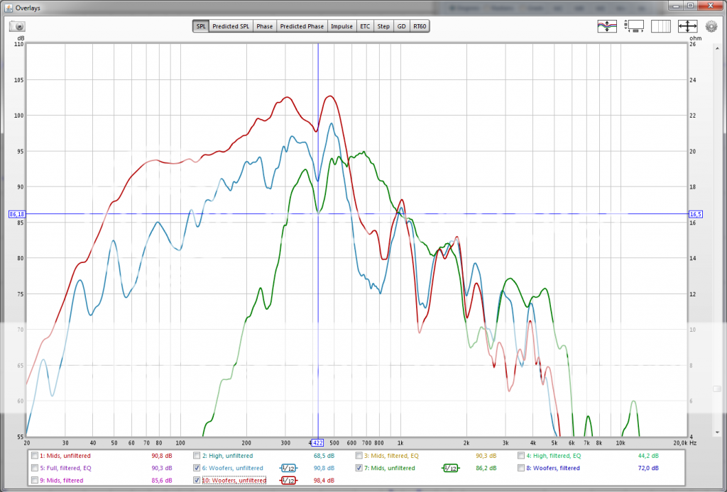
The blue curve is the woofer section, measured @50cm, no reference to 1W or 2.83V whatsoever, that's far too loud!
The green curve is the mids section under the same conditions. Both are fed the same voltage, the 2 woofers are in parallel, the mids are 2S 3P. So it looks like the sensitivity is approximately in the same ballpark.
The top red curve is the woofer section, measured right at the mouth in an attempt to eliminate room modes (obviously I had to turn down the volume, so again, no reference whatsoever).
There's a strange dip around 420 Hz, which corresponds to a wavelength of 81cm, or half a wavelength of 40.5 cm, which is about the depth of the horn, not counting the 6.7 cm inside the compression driver. I haven't seen this dip before I installed the woofers and cut the woofer ports.
And this is what it looks like after I applied a low pass on the woofers @323Hz/But48 and a high pass @323Hz/But24 and low pass @805Hz/But on the mids (still no EQ):
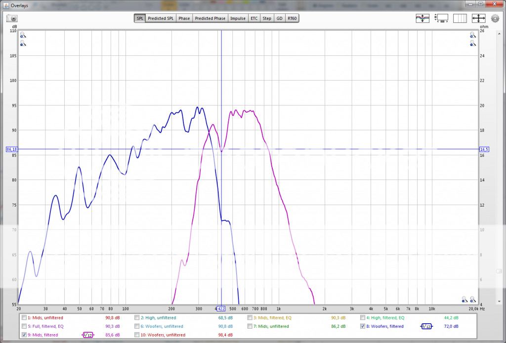
It looks like implementing a port tuned at 110Hz or so wouldn't be a bad idea to try for starters. I don't need the extension to 60Hz or so.
Also, I think there's not much bandwidth left that the mids handle. Would this be a problem or would it improve the power handling of the mids, as I assume they are the weakest link in this construction...
. Here's the unfiltered, un-EQ'ed response:
The blue curve is the woofer section, measured @50cm, no reference to 1W or 2.83V whatsoever, that's far too loud!
The green curve is the mids section under the same conditions. Both are fed the same voltage, the 2 woofers are in parallel, the mids are 2S 3P. So it looks like the sensitivity is approximately in the same ballpark.
The top red curve is the woofer section, measured right at the mouth in an attempt to eliminate room modes (obviously I had to turn down the volume, so again, no reference whatsoever).
There's a strange dip around 420 Hz, which corresponds to a wavelength of 81cm, or half a wavelength of 40.5 cm, which is about the depth of the horn, not counting the 6.7 cm inside the compression driver. I haven't seen this dip before I installed the woofers and cut the woofer ports
.And this is what it looks like after I applied a low pass on the woofers @323Hz/But48 and a high pass @323Hz/But24 and low pass @805Hz/But on the mids (still no EQ):

It looks like implementing a port tuned at 110Hz or so wouldn't be a bad idea to try for starters. I don't need the extension to 60Hz or so.
Also, I think there's not much bandwidth left that the mids handle. Would this be a problem or would it improve the power handling of the mids, as I assume they are the weakest link in this construction...
The poor bandwidth of the mids, only just over an octave wide, is probably going to make the HF driver crossed around 800 Hz the weak link.There's a strange dip around 420 Hz, which corresponds to a wavelength of 81cm, or half a wavelength of 40.5 cm, which is about the depth of the horn, not counting the 6.7 cm inside the compression driver. I haven't seen this dip before I installed the woofers and cut the woofer ports
Also, I think there's not much bandwidth left that the mids handle. Would this be a problem or would it improve the power handling of the mids, as I assume they are the weakest link in this construction...
Six diaphragms that have more excursion compared to one little bugger that also has to go to 16 kHz and will need +10 at the top..
When you tested with four mids, there were dips around 480 Hz and 610 Hz, the upper dip seems to be gone and the lower dip shifted up.
Since the horn geometry has not changed, something else is likely causing the differences.
Are you certain there are no air leaks around the 10" and mids?
The woofers are screwed flat and firmly to the baffle, so no leaks there (they are 12" by the wayAre you certain there are no air leaks around the 10" and mids?
) Sadly, I checked for leaks the first couple of times when I worked on the mids, but after the woofer install I kinda forgot. I was very eager to hear them  .
.Thanks for the tip. Is it possible that a leak in the mids is causing the dip in the LF section? Come to think of it, why not?! They are all coupled into the same horn. Makes sense.
I did try to make the mid ports smaller, hoping it would help them to play a little higher, but the wood filler I used just broke off, so I ended up removing it all again. I'm also not sure smaller ports will not smother the mids.
Despite the issues, I already REALLY enjoy the sound!
It's very natural and full of details.Broken off wood filler, funky plywood, multiple installations, sounds like a recipe for leaks to meThanks for the tip. Is it possible that a leak in the mids is causing the dip in the LF section? Come to think of it, why not?! They are all coupled into the same horn. Makes sense.
I did try to make the mid ports smaller, hoping it would help them to play a little higher, but the wood filler I used just broke off, so I ended up removing it all again. I'm also not sure smaller ports will not smother the mids..
.The lack of HF response looks like the area in front of the mid cones may need to be reduced, in addition to the size of the port holes.
Bondo with fiberglass (it comes pre-mixed, just add the creme hardener) is quite strong, I have used it on horn throats with no breakage.
The area under the cone on the M10 isn't very great, so I'd be tempted to look elsewhere for the cause of the mid's early HF rolloff.
If it were me I'd probably be looking at the position of the mid ports down the horn walls, as it seems quite a distance!
Speaking personally I wouldn't consider putting my port holes at the outer edge of the mids?! as I am normally aiming the other way to get them as close as possible to the HF unit.
Just a thought.
Paul.
The fronts of the woofers have a tap into the horn. The back is just a sealed chamber.Could not tell by the pictures but does the front of the woofers have an entry tap in your horn? Or are the woofers firing into a sealed plenum and your porting the rear of the woofer into the horn?
I had not seen this before so I am very curious is all.
Yeah, you're right. As it is a proto I really didn't do my utter best to make it as pretty as possible, but I agree I should've taken more care making sure all is airtight.Broken off wood filler, funky plywood, multiple installations, sounds like a recipe for leaks to me
The lack of HF response looks like the area in front of the mid cones may need to be reduced, in addition to the size of the port holes.
Bondo with fiberglass (it comes pre-mixed, just add the creme hardener) is quite strong, I have used it on horn throats with no breakage.
Thanks for the Bondo tip, but I haven't seen 'Bondo' here in Europe, so I'll have to look for something similar.
But perhaps it's time for Proto #2
.The area under the cone on the M10 isn't very great, so I'd be tempted to look elsewhere for the cause of the mid's early HF rolloff.
If it were me I'd probably be looking at the position of the mid ports down the horn walls, as it seems quite a distance!
Speaking personally I wouldn't consider putting my port holes at the outer edge of the mids?! as I am normally aiming the other way to get them as close as possible to the HF unit.
Just a thought.
Paul.
The area under the cone is indeed not large, that's actually an understatement. In a second proto I'll start with smaller ports.
I would've loved to be able to put the port holes closer to the throat of the horn, but it's just physically not possible
. I'm already running into troubles with the side mids.Hmmm, a construction a la Paul Spencer just came to mind. I think I'll be looking into his option for mounting 6 mids
 .
.Does it really make a difference to put the holes at the edge of the mids? I mean, even at 1,000Hz a quarter wavelenth is about 8 cm...
Thanks you guys for your input
 . I tend to loose overview sometimes, when I get too close to the subject.
Is it essential that you have 6 mids?
If you could cut it down to 4 it looks like it would be relatively easy to move the mid port entry holes towards the tweeter and get quite a bit more HF extension from the mids.
Btw simple two part car body filler can be used to fill the holes pretty well and try out a different arrangement to see the effects without starting from scratch.
If it must be 6 mids then the only practical option I can see is to open the horn up from the 30 degree angle? to at least 40 degrees or more to give room for the mids to move up the side.
I don't think it makes much difference to have the holes near the edge from the mid's own point of view, but getting the holes up the horn toward the tweeter helps the top response no end (especially with those Visaton M10 drivers).
Paul.
The sims showed far better response with 6 than with 4 (see graphs I posted earlier) and to get to 130dB 4 was not enough. So yeah, I think it is.Is it essential that you have 6 mids?
Ok, thanks for the tipBtw simple two part car body filler can be used to fill the holes pretty well and try out a different arrangement to see the effects without starting from scratch.
 .
.That could prove difficult to fit in the space I have available for transport (they are actually 35 degrees, so 40 is probably not a significant improvement), but if it doesn't work out, I see no other option either.If it must be 6 mids then the only practical option I can see is to open the horn up from the 30 degree angle? to at least 40 degrees or more to give room for the mids to move up the side.
I wasn't aware the M10s are notoriously lacking in the top end? Have I overseen a topic on this on diyaudio (or somewhere else)?I don't think it makes much difference to have the holes near the edge from the mid's own point of view, but getting the holes up the horn toward the tweeter helps the top response no end (especially with those Visaton M10 drivers).
That could prove difficult to fit in the space I have available for transport (they are actually 35 degrees, so 40 is probably not a significant improvement), but if it doesn't work out, I see no other option either.
One option to keep the overall size down while getting the coverage angle up (and providing more space for the side mids) is to reduce the second flare, if space is at a premium then it is probably the best way to achieve it.
It's a slight compromise but I figure these things are all about choosing the best compromise for the job.
If you look at the Danley SH69 it seems to do exactly that and the result is quite a nice compact design.
SH69 | Danley Sounds Labs | Danley Sound Labs, Inc.
I wasn't aware the M10s are notoriously lacking in the top end? Have I overseen a topic on this on diyaudio (or somewhere else)?
No the M10s are certainly not lacking in top end, quite the opposite! hence why I figure your lacking top end is due to port position. In an extreme example I had my M10s going up to 2khz!
Also I was looking at your early graphs with 4 mids and it seemed like their extension went up to 800hz but when you added two more (along the longer side wall - with greater distance to the tweeter) to take it up to the desired 6 the response got smoother but extension seemed to drop to 700hz.
Is that an accurate observation?
Paul.
I already made the second flare smaller than ideal (factor 0,75 instead of 0,65 in bwaslo's SynergyCalc spreadsheet. I suppose I could make it even smaller with relatively little impact on performance.One option to keep the overall size down while getting the coverage angle up (and providing more space for the side mids) is to reduce the second flare, if space is at a premium then it is probably the best way to achieve it.
It's a slight compromise but I figure these things are all about choosing the best compromise for the job.
If you look at the Danley SH69 it seems to do exactly that and the result is quite a nice compact design.
SH69 | Danley Sounds Labs | Danley Sound Labs, Inc.
Nice one, btw, that SH-69. Looks a lot like what I'm trying to do. Except, 116 lbs
. My proto is about half that... I can't make out exactly how they've mounted the mids from the wireframe .That's good to hear. That would mean I should be able to do betterNo the M10s are certainly not lacking in top end, quite the opposite! hence why I figure your lacking top end is due to port position. In an extreme example I had my M10s going up to 2khz!
 .
.I was actually referring to this graph:Also I was looking at your early graphs with 4 mids and it seemed like their extension went up to 800hz but when you added two more (along the longer side wall - with greater distance to the tweeter) to take it up to the desired 6 the response got smoother but extension seemed to drop to 700hz.
Is that an accurate observation?

(6 mids sim)
In comparison with this one:

(4 mids sim)
It seems you looked at the graphs of the measurements I did, and yes, their extension seemed to have dropped after going from 4 to 6
.Cheers
 .
.The mid setup on the SH-69 is basically the same as yours with two mids on each of the wide faces and one on each of the narrow faces. The difference being the 60 degree angle allows a lot more room to get the single mids moved up on the narrow face.
However, extra things worth noting are that the single mids on the narrow faces use two ports per driver, doubling up keeps the holes smaller for the same area, makes the symmetry better and helps reduce the effect of the holes on the tweeter response.
Also from the wireframe you can just see that the midrange ports are put right at the edge of the mids as close as possible to the tweeter entry, no doubt to get as much extension as possible from the arrangement.
I have to be honest I don't actually use any sims myself, I prefer to just build what feels right and measure the result, so the real life measurements appeal a lot more to me! Hence why I was looking mainly at them.
So I'm probably not the right person to comment on the simmed stuff.
Looking at the positioning of the ports on your horn the drop from 800hz rolloff to 700hz from adding the extra mids is along the lines of what I would expect, it's simply down to slight increases in port to tweeter distance (at least that's my view)
Anyway I hope some of this helps.
Paul.
- Status
- This old topic is closed. If you want to reopen this topic, contact a moderator using the "Report Post" button.
- Home
- Loudspeakers
- Multi-Way
- Synergy with BMS 4550, Visaton M10 and ...