
what is "clipping"? how is maximum output voltage? the result which I have got by simulating your circuit is above 20v .Have you solved the clipping problem with darlingtonvas ?
It seems that clipping can blow an amp with buffered vas.
Before my vas current is 5mA ,output voltage is only 15v although my power supply is +-35V .After I increased the vas current to above 10mA ,it runs Ok
I simulated my circuit with vas current 10mA long ago .I will test the thing again
With clipping i mean that the sinus get's cutted on top & bottom
because inputvoltage is too high.
Then diffamp goes to maximum swing, giving easily >100ma in the
buffer before vas. As vastransistor gets into reversebiasing, you
get destructive high basecurrents into vastransistor.
Mike
because inputvoltage is too high.
Then diffamp goes to maximum swing, giving easily >100ma in the
buffer before vas. As vastransistor gets into reversebiasing, you
get destructive high basecurrents into vastransistor.
Mike

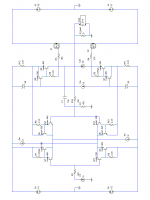
Folded cascodes have somehow slipped out of the thread, so time for another schematic")
I simplified the output stage to just a pair of MOSFETs. So that the cascode stage is capable of driving the output devices, the single transistors have been replaced with Sziklai pairs. Doing the same for the input stage also helps with that. That sort of reverses the reduction in complexity gained from the output stage though. Oh well.
In lieu of an output stage with gain, the supply rails for the output stage need to be lower to maintain rail efficiency. +/-15V won't provide much power, but I just happen to have a suitable transformer lying around for when I come to build it. The voltages could of course be scaled to any values, as long as the transistors can take it. The difference between driver and output stage supply voltages can also be made smaller if the reference voltages provided by X5 and X6 (currently 10V) are reduced. Separate supplies also makes it practical to use a regulated supply for the driver stages, greatly improving PSRR.
I was going to turn it into a fully differential circuit, which would be great with the lower supply voltages, but when it came to applying common-mode feedback it added more complexity than I wanted.
Attachments
Hi, Mr.Evil,
Interesting change you made. You change all front end transistor to CFP transistor. What does it sounds like?
Interesting change you made. You change all front end transistor to CFP transistor. What does it sounds like?
Nice idea, you can look at this http://www.diyaudio.com/forums/attachment.php?s=&postid=334963&stamp=1077770119I was going to turn it into a fully differential circuit
mikeb! At the moment with resistive load ,I can only get about 20mV 2nd .If i use dual differential topo and use a1015 (sure be destroyed) for vas ,i can get 3mv 2ndI think you should always check thd at 20khz and optimize
your circuit for low thd at high freqs.
Generally about harmonics distortion current mirror is the best
mr evil! I remark that using cfp for input and vas can't get the "smooth " when it is turned off or on
Hi thanh !
20mv for 2nd ? That's a bit much for a NFB-topology, you can get
this with openloop ? Normally you can easily get ~1mv.
Maybe this is because of your low biasing in outputstage ?
Mr Evil !
I see that you use symetrical CFP-diffamp without RE's. I already
tried that, it didn't work in real world. Thermal variations were
too big to get stable biasing. You should use at least 22-33ohms,
or use asymetrical topology.
Mike
I do like the CFP; It does seem to end up in everything I make, though usually only the output stage.lumanauw said:Hi, Mr.Evil,
Interesting change you made. You change all front end transistor to CFP transistor. What does it sounds like?[/url]
I haven't built any of the amps here yet. I can't until I've finished my current projects and replenished my supply of small-signal transistors.
That's exactly the sort of thing I was thinking of.lumanauw said:Nice idea, you can look at this http://www.diyaudio.com/forums/attachment.php?s=&postid=334963&stamp=1077770119
Though smooth turn on/off may be desirable, an output relay can be used if it's too bad.thanh said:mr evil! I remark that using cfp for input and vas can't get the "smooth " when it is turned off or on
I can see how that might be a problem. However I was planning on using monolithic matched pairs - I can buy some BC857/847 pairs made by Phillips that are extremely cheap (actually cheaper than two single transistors). I'll have to see if the matching is good enough or not.MikeB said:I see that you use symetrical CFP-diffamp without RE's. I already
tried that, it didn't work in real world. Thermal variations were
too big to get stable biasing. You should use at least 22-33ohms,
or use asymetrical topology.
Mike
yes .My quiescent never is above 10mAMaybe this is because of your low biasing in outputstage ?
john curl said:You folks are starting to scare me!
John,
I would love to see an amplifier design from you for the DIY group. There is a lot of inspiration in just this thread already.
George
After taking a closer look at the schematic lumanauw linked to, I see the topology is all but identical to mine, except it has no global feedback and the common-mode feedback is much simpler than that which I had tried to implement.
So I tried the same on mine - replacing the bias voltage for the cascode stage with a simple resistive divider and feeding back the output to the centre of it. As expected, even order harmonics are right down, but odd order is slightly worse.
So I tried the same on mine - replacing the bias voltage for the cascode stage with a simple resistive divider and feeding back the output to the centre of it. As expected, even order harmonics are right down, but odd order is slightly worse.
Attachments
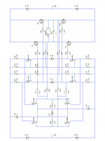
It is true that odd order harmonics sound worse than even, but that does not always mean that an amp with higher odd harmonics will sound worse, since there are other factors to consider. Only once I have built and listened to it will I be able to say if anything untoward is apparent. Fully balanced, symmetrical circuits have great appeal in their elegance, so I would like to build it and see.
Mr Evil said:Fully balanced, symmetrical circuits have great appeal in their elegance, so I would like to build it and see.
Yes i like them too !
Hi thanh !
I've been studying the ad797-topology. It's some tricky currentmirror
enabling gain of 1:5.000.000 !
I've not been sucessful in reproducing this topology, but with a simpler
FC i already got some 1:4.000.000, but with bad bandwidth.
I am still trying, but i think the ad797 is a masterpiece !
But, the ad797 uses asymetric FC, this enables some very tricky
currentmirrors. The datasheet shows a simplified schematic.
Mike
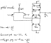
Mr Evil said:From what the datasheet shows, the AD797 is similar to what I would consider the normal folded cascode topology used in op-amps. I have a schematic of one on a piece of paper (from the days before I had a PC). I've scanned it so you can see.
Yes i tried something like that, but this does not enable the OL-gain
of 1:5*10^6 from the ad797.
When i played with mirroring currents like hell, i got this gain.
Mike
- Status
- This old topic is closed. If you want to reopen this topic, contact a moderator using the "Report Post" button.
- Home
- Amplifiers
- Solid State
- Symmetrical folded cascode.