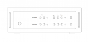
Did you finalize your front panel controls? or still working out the details?

figured I would need more space for controls
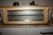
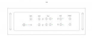
changed the front today, and its crap

need to find some plain alu, and make a complete new control panel
Attachments
maybe this could be fun
Lookin' good.
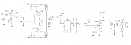
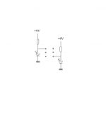
Here's how I ended up doing mine, using the Broskie mono octal board with two 6SN7s, Welborne PS-8 power supply, and my own 6SL7 front end with active mids and bass (Baxandall) between the 6SL7 sections, with a passive treble circuit following the second 6SL7 section.
An externally hosted image should be here but it was not working when we last tested it.
An externally hosted image should be here but it was not working when we last tested it.
Sound clips:
Electric upright, direct to sound card.
Fretless bass guitar, also straight to sound card.
Last edited:
Here's how I ended up doing mine.....
very nice
Im looking for control knobs
where did you find yours ?
only, with two channels I need twice as many
scares me a bit
big risk it will be messy
oh, btw, waiting for a new front plate, smoked poly
a friend said he would get it for me
very nice
I'm looking for control knobs
where did you find yours ?
Thanks, I am pretty happy with how it came out. Those are Jensen transformers on the input and output. I will probably post the whole Spice simulation eventually as I am looking to refine my modeling capabilities and could use some experienced input. I mainly used Spice to get the tone controls in the ballpark of what I was looking for, and it worked very well for that.
Those are Alco/Tyco knobs, sold by many vendors worldwide. I got mine from Marvac for under $2 each, but Small Bear sells them for a bit more as well. Since you're in Europe I assume you will likely do better with someone more local though.
I prefer a clean sound with only small variations
funny thing that the sound needs to be 'correct', and match the music, or I cant play properly
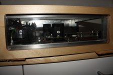
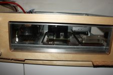
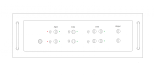
thought it would be better 'rearrange' the inner layout
meaning, the BA3 is moved from output to input, with buffered input att
and then instead have a buffered attenuator output
this also results in solid state gain stage and tube gain stage is shifting places
ought to be better with the solid state stage overdring the tube stage instead of the other way round
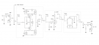
well, not yet finished
hmm, I guess the bypass switches must also kill the output of the bypassed curcuit
meaning, the BA3 is moved from output to input, with buffered input att
and then instead have a buffered attenuator output
this also results in solid state gain stage and tube gain stage is shifting places
ought to be better with the solid state stage overdring the tube stage instead of the other way round
well, not yet finished
hmm, I guess the bypass switches must also kill the output of the bypassed curcuit
Attachments
hmm, because of the possible overdrive situation I may have to reconsider the jfet output buffer
probably wont like it if Im able to overdrive a tube
that is, if it ever happens
anyway, the solution could be two optional output buffers
one jfet, and a tube buffer
man this is getting tricky
probably wont like it if Im able to overdrive a tube
that is, if it ever happens
anyway, the solution could be two optional output buffers
one jfet, and a tube buffer
man this is getting tricky
man this is getting tricky
It does get tricky, for sure. I keep second guessing myself, I have to admit.
Here's an older solid state build of mine. Simplicity, and it measures and sounds great:
An externally hosted image should be here but it was not working when we last tested it.
An externally hosted image should be here but it was not working when we last tested it.
This is based on Rod Elliot's Universal Mixer board, with my own midrange control circuit added. The power amp underneath it is IcePower 1000ASP based.
Yes you could put both a tube and jfet buffer at output.
are you saying it will be ok to have a output jfet buffer after a tube gain stage ?
wait a minute
if I have the att together with the output buffer, as I planned.....then I could still turn down the output, even with a overdriven tube stage, and the 'effect' from the overdriven tube stage would still be present, only 'attenuated'......right ?
he, that was tricky
Maybe just install temporarily to test and finalize later what your ear prefers.
yes yes
just want to get the layout right, so I dont have to change that too much later on
hmm, I guess the bypass switches must also kill the output of the bypassed curcuit
hey, thats just a 2-pole switch, and not complicated at all
one pole bypasses the input signal to the next 'receiver'
and the other pole just 'cuts' the bypassed output
Yes you should be able to capture the mild overdriven tube character, and properly attenuated down it could be fed to the jfet buffer. If you are doing this for bass, and don't want /need multiple stages of massive tube distortion , a jfet buffer would be a simple way to go. Just make sure you add the series cap with proper volts rating to remove the DC after the tube, before your jfet output stage ( I didn't see it in your last schematic).if I have the att together with the output buffer, as I planned.....then I could still turn down the output, even with a overdriven tube stage, and the 'effect' from the overdriven tube stage would still be present, only 'attenuated'......right ?

but maybe I better use 3 pole swithes for the bypass functions
leaving one pole solely for the led indicator
ok, 3PDT it is
with ON/ON toggle function
except for the one at input
it will have ON/OFF/ON function
toggle middle position will be muted input
I hope that will work
- Status
- This old topic is closed. If you want to reopen this topic, contact a moderator using the "Report Post" button.
- Home
- Live Sound
- Instruments and Amps
- Switchable Hi-Z input impedance, how ?