Hi tinitus, you will want to do a ''true bypass'' where the section is switched out completely. I posted a link for the basic wiring. To avoid any ''thump'' sound when you switch over, a 1 meg ohm is sometimes added from signal line to ground on the input to that switched section. The Led occupies 1 section of the triple pole, usually switch to ground and complete the circuit. A cool option is to use a dual LED, like yellow/red and switch in either one depending on which ''channel'' or bypass selected.
A cool option is to use a dual LED, like yellow/red and switch in either one depending on which ''channel'' or bypass selected.

regarding the 1M ohm
I have seen some suggest to short the input of the bypassed curcuit
But I guessed the 'usual' 1M ohm to ground would do the trick
Attachments
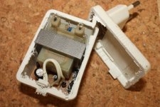
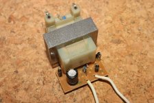
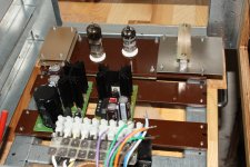
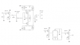
small trafo for the LEDs have now found a new home
and btw, it will have its own mains fuse, so that it dont take out the whole amp in case of errors
which is also part of my point with having both solid state and tube curcuit
should a tube fail, or in need of being replaced, it will still be a fuctional preamp
still need parts for the regulated +/-20V
Attachments
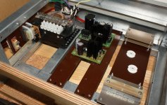
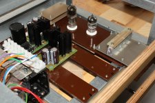
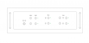
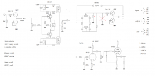
trying to rethink my curcuit/function layout
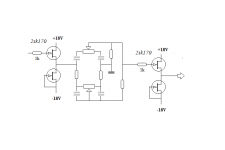
first, the tone control
I suppose it would optimally have a buffer on both input and output
despite the fact thats it means adding further curcuits
and that its best not to place any att in between
buffers will be placed together with the control knobs
all mounted on a small bord behind the front plate
Attachments

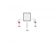
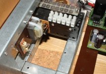
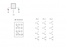
3P4T rotary switch
could be I have solved it now
shoot, no, not quite so simple
maybe better go back to the one with all bypass toggle switches
or a combination
man, thats a tricky one
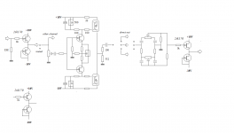
its a 4P ON/ON/ON
but with jumpers made a DP3T
read that jumpers are external and may be cut to make it 4PDT
I do need at least 3P because of the LEDs
but maybe the last 4th pole could work with leaving one of the jumpers
which would make it a mixed 4PDT/3P3T hybrid, or whatever aint switches just a lot of fun
its a 4P ON/ON/ON
but with jumpers made a DP3T
read that jumpers are external and may be cut to make it 4PDT
I do need at least 3P because of the LEDs
but maybe the last 4th pole could work with leaving one of the jumpers
which would make it a mixed 4PDT/3P3T hybrid, or whatever
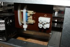
aint switches just a lot of fun and the 4P switching with both jumpers cut
it gives 3 options
and able to 'create' complicated connections
or in other words, it can do signal in/out switching and bypass at the same time
and still have a free pole for LEDs
now I only need to figure out what is the reality
it gives 3 options
and able to 'create' complicated connections
or in other words, it can do signal in/out switching and bypass at the same time
and still have a free pole for LEDs
now I only need to figure out what is the reality
Attachments
- Status
- This old topic is closed. If you want to reopen this topic, contact a moderator using the "Report Post" button.
- Home
- Live Sound
- Instruments and Amps
- Switchable Hi-Z input impedance, how ?