Then the optimum load resistance is 20.44K//100K≈16.97K
What puzzles me is that in a simulation with a 0.68μF coupling capacitor, the distortion spectrum is almost the same as you did obtain, 2nd harmonic at about -86 dB, nevertheless, with a 4.7μF coupling capacitor, 2nd and 3rd harmonics are at about -112 dB.
The AC current through both triodes (almost out of phase) has a phase shift of aboutI notized the same difference in simulated distortion depending on frequency and cap value used.
499.7μs with the 4.7μF cap, and about 497.9μs with the 0.68μF cap.
Maybe 2μs could explain the difference, or it is another defect of simulations?
Popilin, I notized the same difference in simulated distortion depending on frequency and cap value used.
Then I simulated the distortion given from a cap and resistor highpass using the the normal simulation mode of "circuit maker" wich is for the first full 5 cycles of the frequency in question. The distortion decreases with higher cap-values (or increased frequency). Next, I simulated 1 cycle only, givs highest distortion AND a "average dc" component! Next I simulated using the first 50 cycle. Distortion decreases considerable but still some influence of the cap value possible.
Next I simulated 500 full cycles, no difference between caps, minimum distortion. What to make of it? "First cycle" distortion that only shows up in simulations? To my knowledge measurements take the values of much more than only the first few cycles of a frequency
Last edited:
thanks kodabmx.....
FWIW, i stopped building aikidos years ago, the broskie CCDA is better liked by those who i built them for....
user feedbacks seem to indicate that the ccda is sonically more enjoyable...
Interesting, Broskie writes on the website :
Quote: Still, it<CCDA> was no Aikido, sounding only as good as your average $3,000 tube line-stage amplifier ;} I missed the sonic ease and wider sound stage that the Aikido offered.
Popilin, I notized the same difference in simulated distortion depending on frequency and cap value used. <snip>
Agree, average DC component is the key.
THD does not depends on capacitor value, provided that frequency roll-off is OK. At that time, member keantoken explained to me that it is due to DC drift, to solve the problem you must choose longer simulation time, especialy "Time to Start Saving Data" your approach is equivalent.
My old PC force me to reduce capacitor value and not wait ages in each simulation.
actually those who tried the aikido after they heard my ccda said, the aikido was a too honest an amp...the ccda seems to evoke emotions in them...
I have a hard time believing this!
When the only thing I can hear in my aikido is my ALPS BLUE VELVET limitation!!!!
TRUE it is sensitive (the aikido, pre, not the martial art) TO input tube.
Why do I have those military air force N.O.S. matched section 6sn7gtb made in USA in 1960? I have no clue

you need not believe it....after all those were comments from end users...not mine...
when i build stuff, i value the feedback from end users, since it was me who made those amps, i am eager to know what they liked and build up on that...
my goal as a builder is to build amps that are quiet, no hum, no hiss. this is first priority, and a power traffo barely warm to touch....these are my design goals..if i can do that, then i am happy....sonic rewards come after next to that...
IMHO, the Aikido is a CCDA with active loading using tubes, i made one with depletion mosfets in a CCS instead of resistor loading...
Hi tony,
The right part for the right job is never a problem. No cathode - heater potential to worry about either.
-Chris
yes, Chris, designing tube amps and building them, this is a most basic requirement to observe...
you need not believe it....after all those were comments from end users...not mine...
when i build stuff, i value the feedback from end users, since it was me who made those amps, i am eager to know what they liked and build up on that...
my goal as a builder is to build amps that are quiet, no hum, no hiss. this is first priority, and a power traffo barely warm to touch....these are my design goals..if i can do that, then i am happy....sonic rewards come after next to that...
IMHO, the Aikido is a CCDA with active loading using tubes, i made one with depletion mosfets in a CCS instead of resistor loading...
Care to share your schematic of the one you made with depletion mosfets? I would like to build it and then A/B it with my 6SN7/6SN7 Aikido and see what sounds better to my ears.
Pretty neat. I bet it would measure pretty well, especially with a nice linear tube like the 6SN7 or similar. Gain would be pretty much equal to the mu of the tube used.
I have a few 6N16B I should try it with, they are a very linear little tube, and it would only take one bottle per channel, for a very compact little preamp indeed
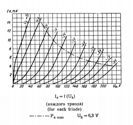
200 volt supply voltage, 100 volts across the tube, ~6mA or so, -2 volts grid looks easy and linear.
Gain would be ~22x or so, might be a good fit for something like a Pass F4 or similar power buffer.
I have a few 6N16B I should try it with, they are a very linear little tube, and it would only take one bottle per channel, for a very compact little preamp indeed
200 volt supply voltage, 100 volts across the tube, ~6mA or so, -2 volts grid looks easy and linear.
Gain would be ~22x or so, might be a good fit for something like a Pass F4 or similar power buffer.
Attachments

Last edited:
Care to share your schematic of the one you made with depletion mosfets? I would like to build it and then A/B it with my 6SN7/6SN7 Aikido and see what sounds better to my ears.
there was a group buy for IXYS 1A depletion mosfets here years ago...
schematics? just replace the tube triodes in the first stage plate load and cathode follower with the depletion mosfets set to 15mA each... and there you have it...
Pretty neat. I bet it would measure pretty well, especially with a nice linear tube like the 6SN7 or similar. Gain would be pretty much equal to the mu of the tube used.
I have a few 6N16B I should try it with, they are a very linear little tube, and it would only take one bottle per channel, for a very compact little preamp indeed

200 volt supply voltage, 100 volts across the tube, ~6mA or so, -2 volts grid looks easy and linear.
Gain would be ~22x or so, might be a good fit for something like a Pass F4 or similar power buffer.
way i see it, greatest plate swing is with a 4mA CCS plate load and 100 v plate and -2.5v grid bias....cathode resistor then is about 620 ohms...
Funny, I had the idea to use IXTH6N50D2 IXYS | Discrete Semiconductor Products | DigiKey instead of tubes and see how it works... Still use an OPT... The input capacitance is attrocious, but the voltage swing is like 2V instead of 70V...
Funny, I had the idea to use IXTH6N50D2 IXYS | Discrete Semiconductor Products | DigiKey instead of tubes and see how it works... Still use an OPT... The input capacitance is attrocious, but the voltage swing is like 2V instead of 70V...
funny and sad, i bought ten of those from a vendor in hong kong and got enhancement mosfets instead...
your post is worthy to pursue in another thread after reading Goatguy's post in another...even Garry Pimm did a mosfet version of his Tabor amp...while i have not seen any schematics i can deduct how he did it using the Tabor amp model...my initial though, when using mosfets in a tubelike output stage such as a Tabor, the gates ought to be driven from a low impedance source, a mosfet buffer is required imho...
Or a BJT buffer. That might work better.
-Chris
sure why not?
David Berning used those in his amps...
there was a group buy for IXYS 1A depletion mosfets here years ago...
schematics? just replace the tube triodes in the first stage plate load and cathode follower with the depletion mosfets set to 15mA each... and there you have it...
If you could post a schematic it would be helpful. Thanks.
If you could post a schematic it would be helpful. Thanks.
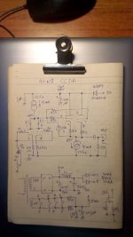
this is all i got....the rest are in my head...
Attachments
- Home
- Amplifiers
- Tubes / Valves
- Survey: Aikido distortion