Had you considered seeing what actual pieces of glass and metal do? Your trust in sims is touching but perhaps not well placed.
Thank you. I am hoping DT will provide the actual data, otherwise it's not useful for practical purpose.
Last edited:
At the risk of being called a Doubting Thomas, these figures look fishy to me. They aren't just good, they're implausibly good for a 12AU7 SRPP. Since the second harmonic is still dominant they imply you could get even better performance with a critical load. I would love to be proven wrong, but to be honest I smell an error somewhere.
Hello Merlin and All,
Merlin at your suggestion I replaced the load resistor with aother value, 22.1K, in place of the 18.45 calculated by Popilin. RuffRecords pointed out as you did in your new book that the 100K analyzer load is in parallel with the load on the breadboard. The test results were several db’s better than with the 18.45K load resistor. There are photos posted below that show that this is a real FFT not a simulation.
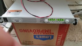
Photo of the 350 volts on the power supply.
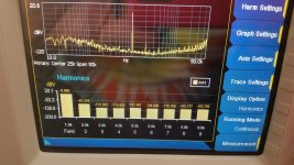
12AU7 1volt out Harmonics photo
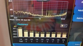
12AU7 5volt out Harmonics photo
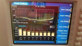
12AU7 10volt out Harmonics photo
Note that the db level of the 1K Hz in the photos is not zeroed out, it is a positive number. You need to count down to zero and then down to the –db numbers for the harmonics on the display. The 1K db number for 1 volt output is the closest to 0, the 2nd Harmonic is near -80db.
DT
Attachments
Last edited:
Very nice, where can I find more info on the spectrum analyser you used? I think you can scan 20V to see if the 2nd harmonic is still dominating , this is the main concern as it is much expected of all PP topologies, thank you.
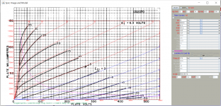
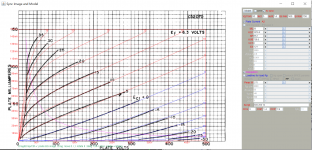
Attached URL is FYI, 9au7 is a version of 12au7a, not 12au7. You may need to tweak the load value is not based on 12au7a so error is expected.
http://www.bunkerofdoom.com/tubes/syl59/DATA/TUBE1959/12AU7_2.JPG
Attached URL is FYI, 9au7 is a version of 12au7a, not 12au7. You may need to tweak the load value is not based on 12au7a so error is expected.
http://www.bunkerofdoom.com/tubes/syl59/DATA/TUBE1959/12AU7_2.JPG
Last edited:
Keysight U8903B
12AU7A 12AU7 9AU7, same same same, just a different heater voltage
http://literature.cdn.keysight.com/litweb/pdf/U8903-90045.pdf?id=2557194&cc=US&lc=eng
12AU7A 12AU7 9AU7, same same same, just a different heater voltage
http://literature.cdn.keysight.com/litweb/pdf/U8903-90045.pdf?id=2557194&cc=US&lc=eng
Last edited:
Keysight U8903B
12AU7A 12AU7 9AU7, same same same, just a different heater voltage
http://literature.cdn.keysight.com/litweb/pdf/U8903-90045.pdf?id=2557194&cc=US&lc=eng
Agreed. I remodeled 12au7 from the previous attached URL datasheet, I found that it's same as 12au7 that our friend supplied 18.55k load. That is correct. The 12au7a model I have is quite difference so I won't use it for the time. So you just need to scan 20V, my FFT data shows that 2nd harmonics no longer dominated at or above 20V out (for your reference only). But never mind if not done.
Here is the 12au7 model I just painted (the grid plate cathode capacitance is not optimised yet), for future ref:
Code:
**** 12AU7A ******************************************
* Created on 05/20/2016 09:25 using paint_kit.jar 3.0
* [URL="http://www.dmitrynizh.com/tubeparams_image.htm"]www.dmitrynizh.com/tubeparams_image.htm[/URL]
* Plate Curves image file: 12au7a.png
* Data source link:
*----------------------------------------------------------------------------------
.SUBCKT 12AU7A 1 2 3 ; Plate Grid Cathode
+ PARAMS: CCG=3P  CGP=1.4P CCP=1.9P RGI=2000
+ MU=20 KG1=2900.9 KP=63.6 KVB=634.2 VCT=4.45 EX=1.47
* Vp_MAX=500 Ip_MAX=150 Vg_step=5 Vg_start=35 Vg_count=14
* Rp=4000 Vg_ac=55 P_max=2.75 Vg_qui=-48 Vp_qui=300
* X_MIN=108 Y_MIN=125 X_SIZE=1198 Y_SIZE=647 FSZ_X=1822 FSZ_Y=877 XYGrid=true
* showLoadLine=n showIp=y isDHT=n isPP=n isAsymPP=n showDissipLimit=y
* showIg1=n gridLevel2=n isInputSnapped=n
* XYProjections=n harmonicPlot=n harmonics=y
*----------------------------------------------------------------------------------
E1 7 0 VALUE={V(1,3)/KP*LOG(1+EXP(KP*(1/MU+(VCT+V(2,3))/SQRT(KVB+V(1,3)*V(1,3)))))}
RE1 7 0 1G  ; TO AVOID FLOATING NODES
G1 1 3 VALUE={(PWR(V(7),EX)+PWRS(V(7),EX))/KG1}
RCP 1 3 1G   ; TO AVOID FLOATING NODES
C1 2 3 {CCG} ; CATHODE-GRID
C2 2 1 {CGP} ; GRID=PLATE
C3 1 3 {CCP} ; CATHODE-PLATE
D3 5 3 DX ; POSITIVE GRID CURRENT
R1 2 5 {RGI} ; POSITIVE GRID CURRENT
.MODEL DX D(IS=1N RS=1 CJO=10PF TT=1N)
.ENDS
*$
Attachments
Last edited:
Your wife is correct.
anatech,
Your wife is correct.
Keysight intends this analyzer is to integrate into a larger system for automated lab and factory floor testing. The front panel works on my small bench as is with my cell phone camera. This thing has GPIB IEEE 488.2 input output and remote control. There is also Lan and LXI function. You can connect a flat screen monitor and hang it on the wall.
I am having fun poking and measuring real world stuff that was only text book stuff to me before.
So far I am getting a crick in my neck using the front panel.
DT
One correction, for 500V is off scale:
Code:
**** 12AU7A ******************************************
* Created on 05/20/2016 10:40 using paint_kit.jar 3.0
* [url=http://www.dmitrynizh.com/tubeparams_image.htm]Model Paint Tools: Trace Tube Parameters over Plate Curves, Interactively[/url]
* Plate Curves image file: 12au7a.png
* Data source link:
*----------------------------------------------------------------------------------
.SUBCKT 12AU7-A 1 2 3 ; Plate Grid Cathode
+ PARAMS: CCG=3P  CGP=1.4P CCP=1.9P RGI=2000
+ MU=20 KG1=1076.2 KP=85.2 KVB=739.8 VCT=0 EX=1.21
* Vp_MAX=500 Ip_MAX=150 Vg_step=5 Vg_start=35 Vg_count=14
* Rp=4000 Vg_ac=55 P_max=2.75 Vg_qui=-48 Vp_qui=300
* X_MIN=108 Y_MIN=125 X_SIZE=1083 Y_SIZE=647 FSZ_X=1822 FSZ_Y=877 XYGrid=true
* showLoadLine=n showIp=y isDHT=n isPP=n isAsymPP=n showDissipLimit=y
* showIg1=n gridLevel2=n isInputSnapped=n
* XYProjections=n harmonicPlot=n harmonics=y
*----------------------------------------------------------------------------------
E1 7 0 VALUE={V(1,3)/KP*LOG(1+EXP(KP*(1/MU+(VCT+V(2,3))/SQRT(KVB+V(1,3)*V(1,3)))))}
RE1 7 0 1G  ; TO AVOID FLOATING NODES
G1 1 3 VALUE={(PWR(V(7),EX)+PWRS(V(7),EX))/KG1}
RCP 1 3 1G   ; TO AVOID FLOATING NODES
C1 2 3 {CCG} ; CATHODE-GRID
C2 2 1 {CGP} ; GRID=PLATE
C3 1 3 {CCP} ; CATHODE-PLATE
D3 5 3 DX ; POSITIVE GRID CURRENT
R1 2 5 {RGI} ; POSITIVE GRID CURRENT
.MODEL DX D(IS=1N RS=1 CJO=10PF TT=1N)
.ENDS
*$
Attachments
Why not just use a pot? Then you can twiddle it and watch the harmonics change, so the sweet spot should be easy to find when the second harmonic is suppressed.Merlin at your suggestion I replaced the load resistor with aother value, 22.1K, in place of the 18.45 calculated by Popilin.
This is my stubborn self.
Okay Merlin you are right. (This is my stubborn self.)
The initial effort was to come close to Popilin’s calculated load resistance with the analyzer input in parallel with some fixed resistance.
So we will see what happens to the shape of the harmonic series. Perhaps there is a different sweet spot for 10volts out vs 1volt.
DT
Why not just use a pot? Then you can twiddle it and watch the harmonics change, so the sweet spot should be easy to find when the second harmonic is suppressed.
Okay Merlin you are right. (This is my stubborn self.)
The initial effort was to come close to Popilin’s calculated load resistance with the analyzer input in parallel with some fixed resistance.
So we will see what happens to the shape of the harmonic series. Perhaps there is a different sweet spot for 10volts out vs 1volt.
DT
the magic resistance is 20.44K ohms
Merlin,
I am Glad that you kicked me into gear this morning. Then Popilin twisted my arm as well.
Here is the short description of the tool. It is sort of like a decade box, but it is not. I used 3 pots in series:
Pot #1 Linear 100K bypassed by a 45.3K resistor, I did not have a 43K. This goes from near 0 Ohms to about 33K ohms.
Pot #2 is a Linear 10K bypassed by a 4.93K resistor, I did not have a 4.4K. This goes from near 0 Ohms to about 3.3K ohms.
Pot #3 is a Linear 10K bypassed by a 309R resistor. This goes from near 0 ohms to about 300R ohms.
Stringing all the pots together makes an adjustable resistor that ranges from near 0 ohms to about 35K ohms. The 3 knobs provide course, medium, and fine adjustment. The fine adjustment was not required. If anyone uses this idea please give me a shout.
I fired up the 12AU7 SRPP breadboard, adjusted the 30-3-300 Adjustable Resistor and fell into a deep distortion notch. I am tired of this today and only ran one FFT at 1.04volts output. The 2nd Harmonic was clocked at -84db. There were no other measurable Harmonics. I turned off everything and Mister Fluke sad the magic resistance is 20.44K ohms for this particular 9AU7 under test today.
Merlin believe it or not.
DT
Why not just use a pot? Then you can twiddle it and watch the harmonics change, so the sweet spot should be easy to find when the second harmonic is suppressed.
Merlin,
I am Glad that you kicked me into gear this morning. Then Popilin twisted my arm as well.
Here is the short description of the tool. It is sort of like a decade box, but it is not. I used 3 pots in series:
Pot #1 Linear 100K bypassed by a 45.3K resistor, I did not have a 43K. This goes from near 0 Ohms to about 33K ohms.
Pot #2 is a Linear 10K bypassed by a 4.93K resistor, I did not have a 4.4K. This goes from near 0 Ohms to about 3.3K ohms.
Pot #3 is a Linear 10K bypassed by a 309R resistor. This goes from near 0 ohms to about 300R ohms.
Stringing all the pots together makes an adjustable resistor that ranges from near 0 ohms to about 35K ohms. The 3 knobs provide course, medium, and fine adjustment. The fine adjustment was not required. If anyone uses this idea please give me a shout.
I fired up the 12AU7 SRPP breadboard, adjusted the 30-3-300 Adjustable Resistor and fell into a deep distortion notch. I am tired of this today and only ran one FFT at 1.04volts output. The 2nd Harmonic was clocked at -84db. There were no other measurable Harmonics. I turned off everything and Mister Fluke sad the magic resistance is 20.44K ohms for this particular 9AU7 under test today.
Merlin believe it or not.
DT
Last edited:
I fired up the 12AU7 SRPP breadboard, adjusted the 30-3-300 Adjustable Resistor and fell into a deep distortion notch. I am tired of this today and only ran one FFT at 1.04volts output. The 2nd Harmonic was clocked at -84db. There were no other measurable Harmonics.
Congratulations!!!


I turned off everything and Mister Fluke sad the magic resistance is 20.44K ohms for this particular 9AU7 under test today.
With or without the analyzer 100K?
The ohm meter was only used across the adjustable resistor.
DT
Then the optimum load resistance is 20.44K//100K≈16.97K
What puzzles me is that in a simulation with a 0.68μF coupling capacitor, the distortion spectrum is almost the same as you did obtain, 2nd harmonic at about -86 dB, nevertheless, with a 4.7μF coupling capacitor, 2nd and 3rd harmonics are at about -112 dB.

The AC current through both triodes (almost out of phase) has a phase shift of about 499.7μs with the 4.7μF cap, and about 497.9μs with the 0.68μF cap.
Maybe 2μs could explain the difference, or it is another defect of simulations?
Popilin,
My understanding is that audio analyzers (FFT) are color blind to phase shift and that SPICE on the other hand is sensitive to phase shift. Doing the math, 0.2us is tiny and not the likely culprit.
I believe the more likely explanation for the difference between SPICE and measurement is complicated by several variables. Even if or especially if you have a perfect valve model you may have perfect canceling. If you do not have a perfect model you still may have perfect simulation canceling. The real glass and metal valves have physical differences from one sample to the next. These differences cannot match an unwavering SPICE model. Then we have the wired in difficulties built into measurement. Measure the same thing twice you have two different measurements. Measure the same thing a hundred times you have an average and a standard deviation.
DT
Audio analyzers can be color blind to phase shift in the signal, but 2nd harmonic cancels if you have AC current from both triodes with same amplitude and perfectly out of phase, 2μs in 500μs means not perfectly out of phase (I mean an angle π)Popilin,
My understanding is that audio analyzers (FFT) are color blind to phase shift and that SPICE on the other hand is sensitive to phase shift. Doing the math, 0.2us is tiny and not the likely culprit.
If you do not want to make another measurement with a bigger cap, it is fine.
Maybe someone else with more curiosity... and an audio analyzer.
This is not totally true, just consider two totally different models, i.e.I believe the more likely explanation for the difference between SPICE and measurement is complicated by several variables. Even if or especially if you have a perfect valve model you may have perfect canceling. If you do not have a perfect model you still may have perfect simulation canceling.
Code:
.SUBCKT ECC82  1 2 3 ; P G C (Triode)
* Mullard data book Jan 1969 AKA 12AU7A 12AU7
* library format: LTSpice 31-May-2008
X1 1 2 3 TRIODE MU=19.98 EX=1.291 KG1=1359.0 KP=87.34 KVB=300.0 VCT=0.00 RGI=2000 CCG=2.3p CGP=2.2p CCP=1.0p ;
.ENDS    ECC82

.SUBCKT JJECC82  1 2 3 ; P G C (Triode)
* JJ Data sheet AKA 12AU7
* library format: LTSpice 01-Jun-2008
X1 1 2 3 TRIODE MU=24.10 EX=1.254 KG1=1023.1 KP=65.28 KVB=300.0 VCT=0.00 RGI=2000 CCG=2.3p CGP=2.2p CCP=1.0p ;
.ENDS    JJECC82

Unfortunately this is just a simulation, but think for a moment, if your post#172 would have published a couple of weeks ago, more than one would have said that you are a liar, even you have published some pictures to prove that you are telling the truth.
@1V RMS -84dB 2nd harmonic with no other measurable harmonics...with an SRPP...and an AU7...nah, that's just possible in simulations.
Last edited:
Note that the db level of the 1K Hz in the photos is not zeroed out, it is a positive number. You need to count down to zero and then down to the –db numbers for the harmonics on the display. The 1K db number for 1 volt output is the closest to 0, the 2nd Harmonic is near -80db.
how did you measure the 1 V is it 1 v p.p or Vrms ?? (trying to find something buggy ja!

- Home
- Amplifiers
- Tubes / Valves
- Survey: Aikido distortion