Its a joy to read your extended sentences sendler!!
I like your ideology about pure signal fom start to finish, how everything interacts to each other, not just exclusive parts somewhere in the midle of the chain.")
How about this pot, is it realy ladder type?
33 Step 10K Volume Control DACT ELMA TKD 2A3 300B tube | Vintage Transformer
Do you build your pots yourself?Where i could get something like instruction and resistor list, but for ladder pot like hereMini-V Resistor Lists
I like your ideology about pure signal fom start to finish, how everything interacts to each other, not just exclusive parts somewhere in the midle of the chain.
How about this pot, is it realy ladder type?
33 Step 10K Volume Control DACT ELMA TKD 2A3 300B tube | Vintage Transformer
...Whatever I build next will use the excellent and affordable Susumu surface mount resistors as they sound better than any through hole resistors in this critical application.
Do you build your pots yourself?Where i could get something like instruction and resistor list, but for ladder pot like hereMini-V Resistor Lists
Attenuators
I sell attenuators but not in this thread.
I am all about helping people get the most amazing sound for the least money with my posts here and don't want to get into trouble with DIYAudio. I post to share. Search the web for stepped attenuators and you will find me.
Its a joy to read your extended sentences sendler!!
I like your ideology about pure signal fom start to finish, how everything interacts to each other, not just exclusive parts somewhere in the midle of the chain.
How about this pot, is it realy ladder type?
33 Step 10K Volume Control DACT ELMA TKD 2A3 300B tube | Vintage Transformer
Do you build your pots yourself?Where i could get something like instruction and resistor list, but for ladder pot like hereMini-V Resistor Lists
I sell attenuators but not in this thread.
I am all about helping people get the most amazing sound for the least money with my posts here and don't want to get into trouble with DIYAudio. I post to share. Search the web for stepped attenuators and you will find me.
Listening for the best attenuator load for direcy out dacs
I listened to my AKM and CS direct out dacs to find the best load for a new stepped attenuator design. I like them into 15k the best. Read about it here.
.
http://www.diyaudio.com/forums/anal...enuator-load-direct-out-akm-cs-dac-chips.html
.
I listened to my AKM and CS direct out dacs to find the best load for a new stepped attenuator design. I like them into 15k the best. Read about it here.
.
http://www.diyaudio.com/forums/anal...enuator-load-direct-out-akm-cs-dac-chips.html
.
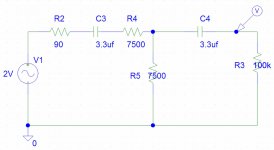
On many outputs with caps in series I have found a down side that a passive pre (attenuator/pot) forms a highpass filter quite quickly, effectively removing the lower end of the response. Have you experienced this?
I mean with say 3.3uF output caps and 15K in parallel you are well in the audio band...
I mean with say 3.3uF output caps and 15K in parallel you are well in the audio band...
F6 2Hz
Looks like the F6 of the roll off of the interactions of the two passive stages with the amp would be about 2Hz. Still pretty acceptable. I have tried many opamps and many different schemes including active bias class A FEToutput buffers following an opamp input and gain stage. Passive direct out through caps with no filter for the dac and passive attenuators at the amp's input sound the most transparent and detailed.On many outputs with caps in series I have found a down side that a passive pre (attenuator/pot) forms a highpass filter quite quickly, effectively removing the lower end of the response. Have you experienced this?
I mean with say 3.3uF output caps and 15K in parallel you are well in the audio band...
Attachments
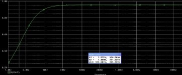
Well in spice sims often look different than in practise. The real truth is measuring what happens with a test tone. I don't know exactly what caused these non linearities, but with a buffer stage followed by the attenuator the problems didn't occur. With the attenuator directly on the source and especially at the lower end of the scale the response dropped quite a bit at the lower end.... Probably something parasitic I overlooked, hence the discrepancy with the spice sim....
Found out how delicate these boards are yesterday night. My chassis-SMPS gounding wire wasn't firmly attached and it disconnected and reconnected (moved away and back to earth ground).
The net result was a puff of white smoke and end of life for the Sure board... Can anyone explain why that occurs?
The net result was a puff of white smoke and end of life for the Sure board... Can anyone explain why that occurs?
my suggestion
I can think of two possibilities. An inductive load could easily pump the positive rail above the power die's Vds rating, which can destroy the chip. Also, the Tripath parts have an internal bootstrap circuit that expects ground to be present when Vdd is applied. If you already have a charged-up low side driver, you risk latchup, which will look a lot like what you saw.
Getting back to your original problem, if you removed the input resistor then you effectively set the gain of the Tripath part to it's physical upper limit. You need to replace that resistor and your volume will be controllable again. You can still shunt the cap if you're absolutely sure there's no chance of DC at the input, but I'd put a nice cap there to be safe.
Found out how delicate these boards are yesterday night. My chassis-SMPS gounding wire wasn't firmly attached and it disconnected and reconnected (moved away and back to earth ground).
The net result was a puff of white smoke and end of life for the Sure board... Can anyone explain why that occurs?
I do not know what happend. But with a switching amp I aspect a capasitive path where current can flow and the amplifier sees a to high supply voltage and blows.
So I think it created a over-voltage on Vcc .
New to sure 2X100. Need advice
I want to use 2 of the 2X100 sure amps to bi-amp my system. I purchased the sure volume control but eventually would like to make a lightspeed attenuator.
Questions:
Has anyone tried to use 1 sure volume control to control 2 amps?
How would you recommend wiring the DC into the 2 boards? like the manual shows? cascading through one unit ti the other or separate leads from the meanwell 24v power supply?
I ruined the solder points for the input caps today. My solution was to wire the new caps to the positive terminal and then to the volume control board. IT Works, but I wonder if I have bypassed the resisitor? I would like to replace the this resistor, What is the best way to do that?
Any help would be greatly appreciated. I am finding it difficult to find what I am looking for in this forum. I know there is a lot if info, but how do you get at it?
Kevin
input resistor
I do see by reviewing the schematic that I have bypassed the resistor. I could insert a 22k resistor between the cap and the volume control, but I believe I would still be bypassing the DIP switches for input resistance. If I am going to use this amp mostly with a Gigaworks DAC should I be using more resistors to recreate the input loading that is suitable?
Thanks for any help you can offer
Kevin
Got an amp.
It's working! I've run it for hours and unfortunately the fan is on quite fast, too fast and a bit noisy, too noisy.
Anyone went passive cooling with these new boards? Beside silence, the 5V will be less noisy, removing related parts. A tiny gain in heat maybe (12V regulator on 32V).
Having OsCon 180µF/20V SP in hands, is it worth replacing the SMD cap for this one on the 5V?
Matthieu
Hi All, I have a spare MeanWell PSU that Sure sell to go with this module, its here in the UK so no waiting from china.
MEANWELL MEAN WELL DC Power S-350-24 24V/14.6A/350W UK on eBay (end time 27-Feb-11 23:19:46 GMT)
MEANWELL MEAN WELL DC Power S-350-24 24V/14.6A/350W UK on eBay (end time 27-Feb-11 23:19:46 GMT)
Hi All, I have a spare MeanWell PSU that Sure sell to go with this module, its here in the UK so no waiting from china.
Sorry this is the proper add !
MEANWELL MEAN WELL DC Power S-350-24 24V/14.6A/350W UK on eBay (end time 27-Feb-11 23:19:46 GMT)
Hi all,
just found out this board on ebay and this topic after some search
I didn't get into tripath since one I made some years ago with the 2*25w chip. (I used 41hz boards)
I was very satisfied with it but unfortunately now I do not have the time to fully realize an amp like this
Thats why I'm interested in this ready to box board but I have some questions; maybe you have answers !
There is a 4*100w board : 4*100W TK2050 TP2050 Tripath D-class Amplifier Board en vente sur eBay.fr (fin le 28-févr.-11 08:21:32 Paris)
From the short view I had of the topic, I see you speak only about the 2*100w, but this one is almost the same price and fanless, isn't it better ?
Also, can these board fit this case for instance ? Audio Amplifier DIY Suite ?Volume Control IC en vente sur eBay.fr (fin le 25-févr.-11 19:25:46 Paris)
It seems done for it but it seems very small to me.
Last question, is a 2*100w powerfull enough to power an outdoor sound system ?
Many thanks guys for your help.
Cheers from france
Passive cooling
I've used passive cooling with the previous board which had a fan running at 5 volts continuous and passive cooling works fine. I used a Ainex Northbirdge heatsink. Zalman makes a similar one. Both will fit. Here is the link to a site where my build was featured. http://www.justblair.co.uk/gregs-2x100watt-tk2050-amplifier-project.html You can see what I did there.
Greg
Greg
http://www.justblair.co.uk/gregs-2x100watt-tk2050-amplifier-project.html
Got an amp.
It's working! I've run it for hours and unfortunately the fan is on quite fast, too fast and a bit noisy, too noisy.
Anyone went passive cooling with these new boards? Beside silence, the 5V will be less noisy, removing related parts. A tiny gain in heat maybe (12V regulator on 32V).
Having OsCon 180µF/20V SP in hands, is it worth replacing the SMD cap for this one on the 5V?
Matthieu
I've used passive cooling with the previous board which had a fan running at 5 volts continuous and passive cooling works fine. I used a Ainex Northbirdge heatsink. Zalman makes a similar one. Both will fit. Here is the link to a site where my build was featured. http://www.justblair.co.uk/gregs-2x100watt-tk2050-amplifier-project.html You can see what I did there.
Greg
Greg
http://www.justblair.co.uk/gregs-2x100watt-tk2050-amplifier-project.html
- Status
- This old topic is closed. If you want to reopen this topic, contact a moderator using the "Report Post" button.
- Home
- Amplifiers
- Class D
- Sure Electronics New Tripath Board tc2000+tp2050