They sound amazingly good, when you get one that works! Item Audio swapped out my first board . . . they're really PSU-sensitive (as you might expect). You'll probably experience a transformation when you can slot in a better power supply
Hi, please see the attached two pics.
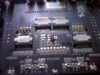
Taking note of the heatsink photo you can clearly see that three components have suffered heat failure. These are the TP2050 chips for channels 1 and 4 and the regulater chip. The question is what went first and why? Note also that more than sufficient heat transfer paste has been applied.
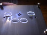
The second photo is out of focus but look at the left most chip. It is the TP2050 chip for channel 1. Notice that around 1/3 of the chips heat conductive surface was not touching the heatsink.
Now, my (still working at it) hypothesis is this.
At manufacture the daughter board is fixed to the main board and the header pins connecting the two are soldered. It is now solidly fixed in place.
Next a good amount of heat transfer paste is applied to all four chips and the heatsink is bolted on. In some boards the heatsink is bolted with sufficient force to cause the boards to flex. This is caused by the header pins being soldered in a minute fraction such that they are just a little tiny bit too high. The main board on mine was flexed enough to bow the main board my several mm. This force is enough to cause channel 1 TP2050 to come away from the heatsink by a tiny amount. This is enough to cause the chip to loose 1/3 of it's heat transfer area.
To make the problem worse, the TC2000 chips are located under channels 1 and 4 TP2050 chips adding to the heat problem. The heat builds and at some stage a catostrophic failure occurs taking the other chips with it. Both TP2050 chips for channels 1 and 4 are under increased heat load due to the location of the TP2000 chips which, being sandwiched between the two boards, has no chance whatsoever to dissipate any heat at all. The heat just builds until failure.
A solution would be three fold.
Redesign the daughter board such that the two TC2000 chips have some air circulation so they can dissipate heat.
Fix the heatsink to the daughter board before soldering the header pins to the main board.
Provide two more central fixing point for the heatsink to avoid the flex problems.
Any comments are welcome, please.
Terry
Taking note of the heatsink photo you can clearly see that three components have suffered heat failure. These are the TP2050 chips for channels 1 and 4 and the regulater chip. The question is what went first and why? Note also that more than sufficient heat transfer paste has been applied.
The second photo is out of focus but look at the left most chip. It is the TP2050 chip for channel 1. Notice that around 1/3 of the chips heat conductive surface was not touching the heatsink.
Now, my (still working at it) hypothesis is this.
At manufacture the daughter board is fixed to the main board and the header pins connecting the two are soldered. It is now solidly fixed in place.
Next a good amount of heat transfer paste is applied to all four chips and the heatsink is bolted on. In some boards the heatsink is bolted with sufficient force to cause the boards to flex. This is caused by the header pins being soldered in a minute fraction such that they are just a little tiny bit too high. The main board on mine was flexed enough to bow the main board my several mm. This force is enough to cause channel 1 TP2050 to come away from the heatsink by a tiny amount. This is enough to cause the chip to loose 1/3 of it's heat transfer area.
To make the problem worse, the TC2000 chips are located under channels 1 and 4 TP2050 chips adding to the heat problem. The heat builds and at some stage a catostrophic failure occurs taking the other chips with it. Both TP2050 chips for channels 1 and 4 are under increased heat load due to the location of the TP2000 chips which, being sandwiched between the two boards, has no chance whatsoever to dissipate any heat at all. The heat just builds until failure.
A solution would be three fold.
Redesign the daughter board such that the two TC2000 chips have some air circulation so they can dissipate heat.
Fix the heatsink to the daughter board before soldering the header pins to the main board.
Provide two more central fixing point for the heatsink to avoid the flex problems.
Any comments are welcome, please.
Terry
Attachments
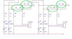
I don't have one of these boards but looking at the diagram I see 100k resistors to ground after the input caps. This will give dc through the amp..
And no input caps via input blocks..
Sorry, no they don't, they just set the input impedance.
Terry
Both problems have now been addressed.
From Sure:
Thank you so much for your mail.
We have introduced your design in the development of this amplifier board. We have removed R6,R7,R8 and R9 and replaced R12,R13,R16 and R17 with monolithic capacitors so that there will be more space.
We are grateful for your support.
From Sure:
Thank you so much for your mail.
We have introduced your design in the development of this amplifier board. We have removed R6,R7,R8 and R9 and replaced R12,R13,R16 and R17 with monolithic capacitors so that there will be more space.
We are grateful for your support.
Both problems have now been addressed.
From Sure:
Thank you so much for your mail.
We have introduced your design in the development of this amplifier board. We have removed R6,R7,R8 and R9 and replaced R12,R13,R16 and R17 with monolithic capacitors so that there will be more space.
We are grateful for your support.
Hi, Audio1st, could you please explain how this resister can put DC through the amp. IN all amps I've seen (Class A or AB) a resister at this point sets the input impedance. How does it work in a class D.
Should those with current boards make these mods?
Thanks, Terry
Hi Terry,
If you think of it as an amp with a +/- 2.5Vdc supply. GND is connected to the -2.5Vdc supply. The actual 0V point is the bias cap pin. That is why you must use an input cap (dc blocker), after any input connection to GND.
The 100k resistor is not the main problem, Sure may have been able to dial out the dc from this with the trimmers?
The main problem would be shorting the terminal block inputs to GND with say a pot. If you use the rca inputs, then there should not be a problem..
Barry.
Attachments
Last edited:
Hi Terry,
If you think of it as an amp with a +/- 2.5Vdc supply. GND is connected to the -2.5Vdc supply. The actual 0V point is the bias cap pin. That is why you must use an input cap (dc blocker), after any input connection to GND.
The 100k resistor is not the main problem, Sure may have been able to dial out the dc from this with the trimmers?
The main problem would be shorting the terminal block inputs to GND with say a pot. If you use the rca inputs, then there should not be a problem..
Barry.
Thanks Barry, that is good to know. I was using the block inputs with a pot. Next board I would like to add more input caps, I was thinking of high grade 2.2uF, any thoughts! Should those with the current boards make any mods. Obviously from what you have said, they should add input caps if using the terminals and this is easy by just hanging them off the terminal blocks.
Once again, thanks. These are great, easy to use boards with a great form factor. They sound good and are very quiet.
Terry
So, should R6,R7,R8 and R9 be removed even when using the RCA-connectors? (They seems to be located under the heat sink)
//Christian
Hi Christian,
It depends on how much dc you have at the speaker terminals.. If the dc offset has been adjusted with those resistors in place and you remove them, you may then have worse dc offset.
The dc offset trimmers I think are under the heatsink, so to re-adjust them the heatsink would have to be off. I don't know if the chips could cope with that?
If you can measure the dc offset please let use know the figures.
Barry..
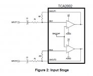
post 69: is input 2 connected to the correct end of Rf?
No... looks like the image was mirrored but not the opamp.....
post 69: is input 2 connected to the correct end of Rf?
You are probably right Andrew, but it is taken straight from the Tripath App sheet..
Input 2, Ri should connect to INV2..
My 2 cents about Tripath Board 4*100W class-D ver 1.1
This is the equipment.
Wallwart Switching PSU 24 Volts at 26 Volts.
Tripath Board 4*100W with a 12 volts fan running at 5 volts on top
B&W 685 BI AMPLIFIED
DIY Lightspeed Passive Attenuator
PC nforce 2 windows xp analog ouputs, ASIO driver , playing Mp3 and flac.
This amp Sounds really clear, and with great soundstage, crystal clear compare to my yamaha HT 5.1 receiver. The only thing I don´nt like, is that the tweeters sound a little hard, and the music sound to technical. MI think that a Gain Buffer (tube or discrete) after the attenuator will help. Any opinions? ...
Cable length?
How long are the cables after the pre? Passive volume controls don't like much cable after them. I use none with my attenuators plugged right into the amps inputs.
My 2 cents about Tripath Board 4*100W class-D ver 1.1
This is the equipment.
Wallwart Switching PSU 24 Volts at 26 Volts.
Tripath Board 4*100W with a 12 volts fan running at 5 volts on top
B&W 685 BI AMPLIFIED
DIY Lightspeed Passive Attenuator
PC nforce 2 windows xp analog ouputs, ASIO driver , playing Mp3 and flac.
This amp Sounds really clear, and with great soundstage, crystal clear compare to my yamaha HT 5.1 receiver. The only thing I don´nt like, is that the tweeters sound a little hard, and the music sound to technical. MI think that a Gain Buffer (tube or discrete) after the attenuator will help. Any opinions? ...
How long are the cables after the pre? Passive volume controls don't like much cable after them. I use none with my attenuators plugged right into the amps inputs.
Mods
http://www.diyaudio.com/forums/clas...ipath-board-tc2000-tp2050-54.html#post1935648
All of the mods from the 2X100 will apply to your board though your coils are already a bit better than what the 2X100 comes with.I was running a feet long cable,now I change to a 3 inch long and there is a very hi difference in noise without source, almost disapear. I think the bass improve a little bit also. Next plan to solder to the amp. thanx a lot, any other idea?
http://www.diyaudio.com/forums/clas...ipath-board-tc2000-tp2050-54.html#post1935648
Both problems have now been addressed.
From Sure:
Thank you so much for your mail.
We have introduced your design in the development of this amplifier board. We have removed R6,R7,R8 and R9 and replaced R12,R13,R16 and R17 with monolithic capacitors so that there will be more space.
We are grateful for your support.
I just got one of the updated boards. Not happy. The changes to my board were clearly made after the original fabrication and done very sloppily. Flux all over, sloppy solder joints, two cold joints, one lead bent over until it touches the one next to it. Yuck ...
Worse, though, is that the capacitors used to replace R12,13,16,17 are tiny little monolithic ceramics.
Not the kind of thing you want to see in the signal path. They're under the daughterboard, so there's no space for anything bigger and no way to get to them to replace. Ugh - Status
- This old topic is closed. If you want to reopen this topic, contact a moderator using the "Report Post" button.
- Home
- Amplifiers
- Class D
- Sure Electronics New Tripath Board 4*100W class-D Amplifier Board