Just read one page back somebody claimed that different reference cap produces different sound.
It has been documented that Bi-polar electrolytic caps have lower distortions than polarised electrolytic caps. There are a plenty of Panasonic ECE-A1EN101U 25V 100uF Bi-polar caps available.
ECE-A1EN101U Panasonic Electronic Components | Capacitors | DigiKey
But checking out the data sheet, the bi-polar cap may have 3+ times leakage current.
Is low leakage required for the capacitors in the Jung Supereg?
Also, the datasheet does not provide information about ESR / impedance. Do bi-polar caps have higher impedance?
Just simulated in LTSpice. Low leakage or high leakage seemed to make little difference (less than 0.05dB difference) to the results. This is unlike in a capacitor multiplier in which the leakage in the reference cap can make a huge difference.
I also found that higher impedance of the caps make little difference (contrary to what AWL's description in his document).
So I guess bi-polar capacitors should suit in the Jung Supereg.
Correct me if I am wrong.
I also found that higher impedance of the caps make little difference (contrary to what AWL's description in his document).
So I guess bi-polar capacitors should suit in the Jung Supereg.
Correct me if I am wrong.
Last edited:
The simple answer is no. Compare also the BOM with recommended parts.Is low leakage required for the capacitors in the Jung Supereg?
Just read one page back somebody claimed that different reference cap produces different sound.
[snip]
It has been documented that Bi-polar electrolytic caps have lower distortions than polarised electrolytic caps.
But the ref cap has DC on it. How can it 'distort' DC?
Jan
When tested as a filter.................It has been documented that Bi-polar electrolytic caps have lower distortions than polarised electrolytic caps.................
A correctly sized DC blocking capacitor should not be used as a filter of the wanted frequencies. That would be applying EQ.
When an electrolytic has vriually no AC signal across (not a filter) then the added distortion is virtually zero.
Now back to the testing when used as a filter:
The test report shows a lower level of distortion when back to back polar electrolytics are used instead of a single polar.
The report also shows a lower level of distortion when back to back bi-polar electrolytics are used instead of a single bi-polar.
In all of these tests the AC signal across the capacitor has to be made high to beable to measure the distortion.
It seemed to me in reading the report and the methodology that he was near the limits of distortion detection when meauring the plastic and double bi-polars.
I suspect the quite advanced methodology adopted would not detect any added distortion from double electrolytics if the AC signal across the DUT caps was reduced to similar levels that we see in normal DC blocking duty.
I further suspect that even the single polar electrolytic may also have added distortion that is below the detectable levels for virtually zero AC signal. But I have never seen any test reports for this duty.
Last edited:
I'm puzzled by the Diyaudio store schematic showing the remote sense components as 100R 100pf. Walt earlier refers to 10 ohms and 0.01 uf and some tolerance for individual loads might be nessecary. 100 R seems too high and upsetting of the matched resistance of the input stage.
I used 10R, Panasonic ECG type and connected the "Sense" at the end of the power rail using shielded cable.
For the Adcom GFP-565 I used the Old Colony printed circuit boards (designed by Jan back in the dark ages of Flemish painting.)
An externally hosted image should be here but it was not working when we last tested it.
For the Adcom GFP-565 I used the Old Colony printed circuit boards (designed by Jan back in the dark ages of Flemish painting.)
I use 4R and 10nF. The 10nF is connected to the rail, not ground. The RC is for the remote sensing wire being 60mm long connected to small elongated power plane. It works well. Without the RC, there was some mild ringing.
I am now redoing the PCB design and want to put the Jung regulator right at the load of a elongated power plane.
I am not sure if I still need the remote sensing RC because the distance to the elongated power plane will be around 10mm. I simulated in LTSpice and found that when the inductance is low the RC is not needed. But I am not sure.
Can the experts guide me on this one? Thanks a million.
Last edited:
Question about the placement of "dummy load".
Say, a preamp circuit, e.g. a single opamp buffer, run on dual rails draws a very small amount of current, e.g. 5mA, and the +/- Jung Superegs have a "dummy load" of 100mA to lower the output impedance of the regulators. In this case the dummy load current is 20 times larger than the load current.
Would you put the dummy loads right at the regulator outputs to dump the current to the reference ground? - this would have the shortest current loop. Alternatively, would you ground the dummy loads away from the reference ground with a longer current loop?
In other words, would the dummy load current make the reference ground dirty?
After first thought I would say NO because the output of the Jung Supereg is quiet and the dummy load current is DC so the grounding point should be free of AC noise. After second thought I am not so sure because the positive rail voltage may not be exactly the same as the negative rail voltage so the unbalanced current might create some voltage offset at the circuit reference ground point?
I guess the dummy load currents can create ground current due to imbalance but such ground current is constant current (at DC) so it may have no impact on sound.
Please shed some lights on this.
Last edited:
Is LM 4040 reference good replacement for LM329?
Assuming you use a ref filter I don't see any practical difference. The advantage of the 4040 is that it is available in varies accurate voltages.
I have an application where I use a 4.096V version, 0.1%, and it cost less than 50 cents.
Jan
Assuming you use a ref filter I don't see any practical difference. The advantage of the 4040 is that it is available in varies accurate voltages.
I have an application where I use a 4.096V version, 0.1%, and it cost less than 50 cents.
Jan
You could always use a "standard cell" if your country allows the use of mercury.
Need a little help.
I set up R14 and R7 as 1k for 12v output with R13 and R6 set to 750 ohm.
The zener is 6.8v and the LM329DZ is 6.9v. Only getting 7.77v at the output.
I tried to flip the values of say R14 and R7 thinking I had "top" and "bottom" mixed up, but it made no difference.
Ran a test on the positive side with an adjustable lab DC supply. The voltage increased at the output until it hits 7.77v, the lab supply could be increased further but the reg output stays at 7.77v.
I didn't connect the sense leads. What the proper way to connect them in a test? I tried to jumper the sense but the output was almost equal to the input voltage, even beyond 12v.
Used all the exact values except c12/11 which is 180pF. It's what I had on hand.
Thanks in advance,
Vince
Last edited:
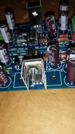
The BJTs are facing the wrong way, aren't they?
The silk screen is misleading, if they are in the wrong way.
Also the Galo 1995 article recommended raw dc power supply looks wrong as well. The negative section look exactly like the positive section. The cap isn't reversed in the negative section, and probably wrong at the bridge as well. I'm not sure about this so don't chew me out. I guess it depend on what reference is...
Attachments
The BJTs are facing the wrong way, aren't they?
The silk screen is misleading, if they are in the wrong way.
Also the Galo 1995 article recommended raw dc power supply looks wrong as well. The negative section look exactly like the positive section. The cap isn't reversed in the negative section, and probably wrong at the bridge as well. I'm not sure about this so don't chew me out. I guess it depend on what reference is...
I am not at home right now but I seem to remember that the pass transistor heat tab faced outward.
See the pic in the diyaudio store.
Another check is to measure the ref voltage.
Jan
Last edited:
- Home
- The diyAudio Store
- Super Regulator