6.5 inch Buyout Bass Driver as 2=Way?
I'm late arriving to this thread and new to the Unity and thought that this would be the best match for my question. I am toying with the Parts Express buyout 6.5 in polycone woofer ($5 ea). It has a relatively high Qts of about 0.95 which makes it a good candidate for getting deeper bass extension in a sealed box. My goal is to make a 2-way Unity so that I can bi-amp with line-level XO. I want to use this for home listening so no high SPL's are needed and I was aiming for about 90dB efficiency at 2.83V and 1 meter.
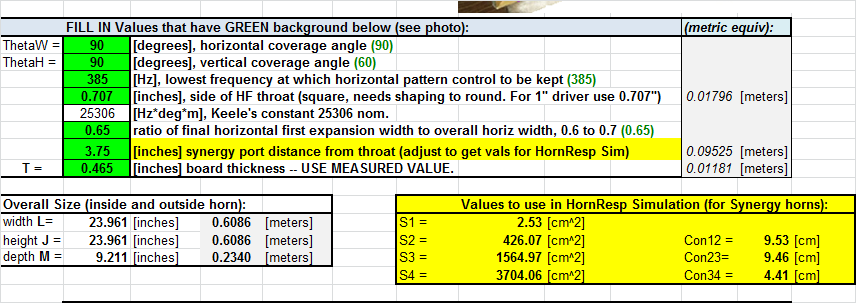
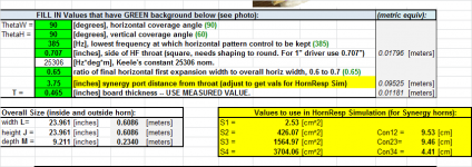
I started with Bwaslo's spreadsheet and basically used his default design except that I made it a 90 deg x 90 deg horn instead of 90x60.
Here is the screenshot of the input and outputs for simulation. Reason for this is that all panels will be the same and easier for me to make. Also, it provides room for future upgrade to an 8 driver version.
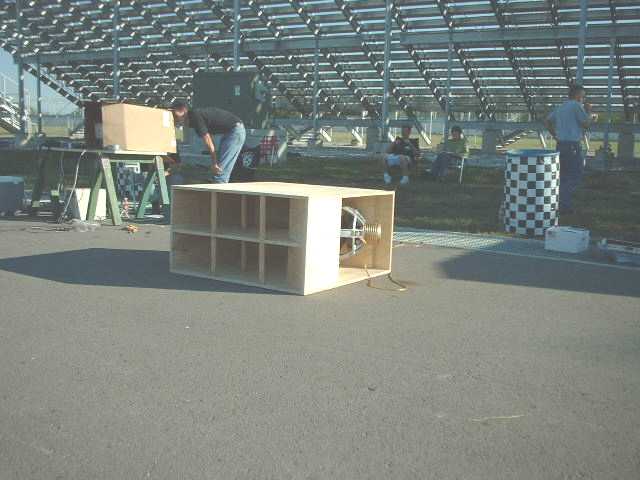
I then made a model in AkAbak for a qnty 4 driver horn with the drivers placed at about the midway point from the CD throat and the angle change of the diffraction edge. I am using 2.5 in dia holes for the bass injection ports from the drivers. I am including the approximate volume of the driver cone behind the port. The enclosure is externally 25 in high x 25 in wide x 16 in deep to provide the volume needed for the four drivers. Since it is a sealed back alignment there won't be any bass reflex port phase issues.
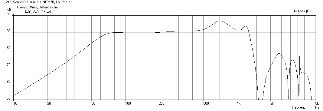
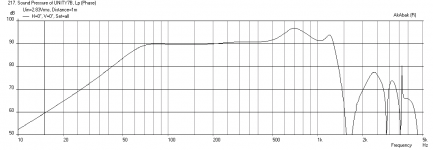
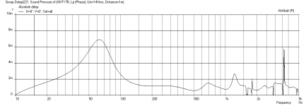
Here is the SPL vs freq with just the bass drivers. I had to add a 12 ohm & 2.4 mH inductor in parallel to tame the rising response. It is pretty good except for the bump near 700 Hz. This bump can be reduced by placing the bass injection port closer to the mouth but the tradeoff is less HF extension ;(will requite a mid driver in a 3-way) The response is predicted to be 59 Hz to 1.3 kHz -3dB. I think this will easily let me use a XO at 1 kHz to 1.2 kHz which works for many different CD's.
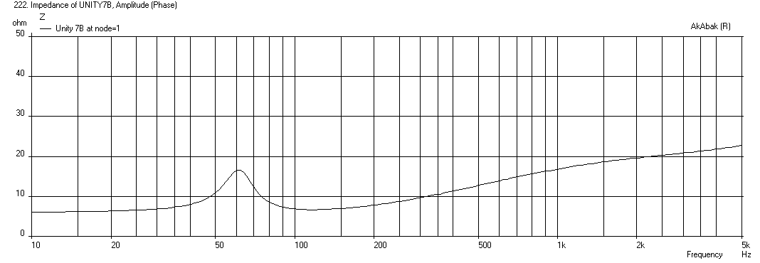
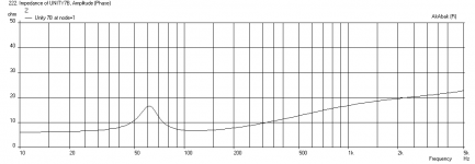
The impedance looks pretty good:
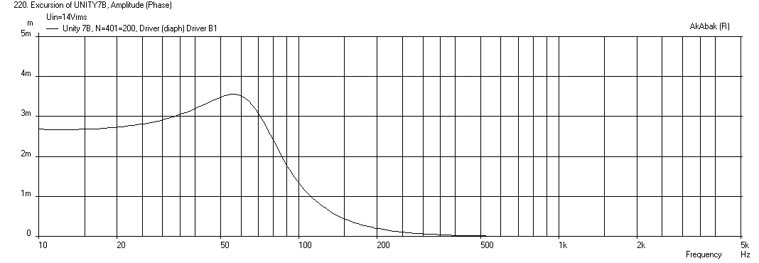
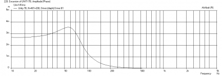
Here is the max cone excursion at about 14 volts rms.
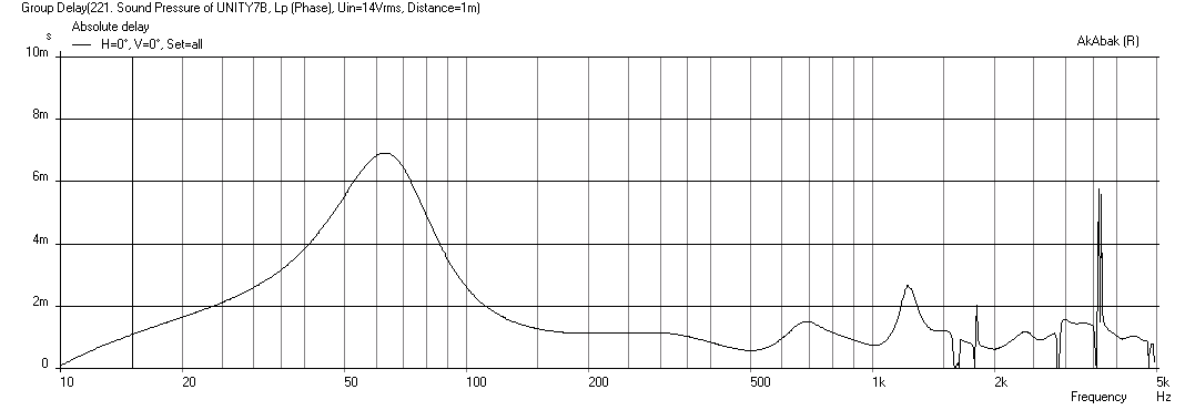
Here is the group delay - excellent from 100 Hz to 1KHz, and not too bad at 60 hz.
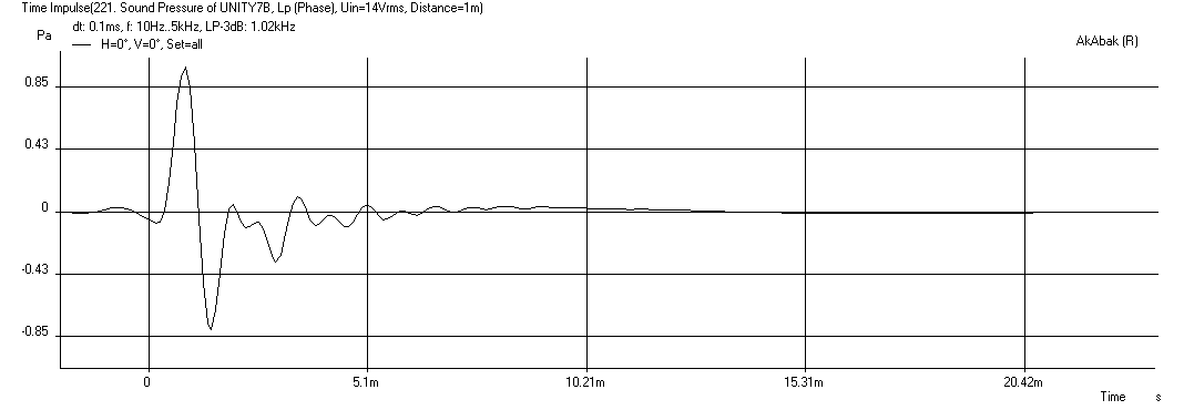
Here is the impulse response - pretty clean.
Let me know what you guys think - is this 2-way approach viable and what can I do better?
Thanks in advance.
Regards,
Xrk971
I'm late arriving to this thread and new to the Unity and thought that this would be the best match for my question. I am toying with the Parts Express buyout 6.5 in polycone woofer ($5 ea). It has a relatively high Qts of about 0.95 which makes it a good candidate for getting deeper bass extension in a sealed box. My goal is to make a 2-way Unity so that I can bi-amp with line-level XO. I want to use this for home listening so no high SPL's are needed and I was aiming for about 90dB efficiency at 2.83V and 1 meter.
I started with Bwaslo's spreadsheet and basically used his default design except that I made it a 90 deg x 90 deg horn instead of 90x60.
Here is the screenshot of the input and outputs for simulation. Reason for this is that all panels will be the same and easier for me to make. Also, it provides room for future upgrade to an 8 driver version.
I then made a model in AkAbak for a qnty 4 driver horn with the drivers placed at about the midway point from the CD throat and the angle change of the diffraction edge. I am using 2.5 in dia holes for the bass injection ports from the drivers. I am including the approximate volume of the driver cone behind the port. The enclosure is externally 25 in high x 25 in wide x 16 in deep to provide the volume needed for the four drivers. Since it is a sealed back alignment there won't be any bass reflex port phase issues.
Here is the SPL vs freq with just the bass drivers. I had to add a 12 ohm & 2.4 mH inductor in parallel to tame the rising response. It is pretty good except for the bump near 700 Hz. This bump can be reduced by placing the bass injection port closer to the mouth but the tradeoff is less HF extension ;(will requite a mid driver in a 3-way) The response is predicted to be 59 Hz to 1.3 kHz -3dB. I think this will easily let me use a XO at 1 kHz to 1.2 kHz which works for many different CD's.
The impedance looks pretty good:
Here is the max cone excursion at about 14 volts rms.
Here is the group delay - excellent from 100 Hz to 1KHz, and not too bad at 60 hz.
Here is the impulse response - pretty clean.
Let me know what you guys think - is this 2-way approach viable and what can I do better?
Thanks in advance.
Regards,
Xrk971
Attachments
-
 Synergy-90x90deg-Bwaslo-Spreadsheet.png37.9 KB · Views: 673
 -
 Synergy-90x90deg-Buyout-Freq-1m.png27.2 KB · Views: 663
 -
 Synergy-90x90deg-Buyout-Impedance.png24.9 KB · Views: 660
 -
 Synergy-90x90deg-Buyout-Displ-max.png26.5 KB · Views: 654
 -
 Synergy-90x90deg-Buyout-GD.png27.6 KB · Views: 670
 -
 Synergy-90x90deg-Buyout-Impulse.png16.5 KB · Views: 643
Last edited:
Wow I wish I could answer your questions. I have used Bwaslo's spreadsheet also to determine what my horn cut off will be but need to know how to simulate.
Is Akabak the only way to simulate a driver with a small front volume and ported rear such as is in a SH 3way? I don't 6th order would be the same thing but I am trying to get an idea of performance.
I am trying to decide between which 15's I want to use in my build. Both are very similar in spec but wanted to see a simulation. I am also getting the woofers by sea so they wont be here till middle of January. In that time I would like to simulate the response if I can. I am still going with a SH64 style design. Although I may end up with a SH64 with dual 15s not quad.
Is Akabak the only way to simulate a driver with a small front volume and ported rear such as is in a SH 3way? I don't 6th order would be the same thing but I am trying to get an idea of performance.
I think Akabak will be needed if you intend to combine the bass reflex output from the rear of the bass driver in combination with the small compression chamber followed by injection into a arbitrary horn. It is not that hard to use Akabak if you give it a try and start with a model someone provides you. Get me the driver T/S specs and the Bwaslo spreadsheet inputs for the SH64 and I will see what I can do to sim it for you. I have been trying some ported BR options with the Unity/Synergy and it gives you extension but messes with the GD. One thing I have noticed is that in conventional horn loaded speakers, you want powerful low Qts motor drivers, but for the Unity/Synergy I am not seeing that is always the best choice and higher Qts drivers may provide deeper bass extension and have smoother response in that the driver is dominated by the horn's geometry rather than able to over-power it and impose its own resonance effects - consistent with comments made by JLH in previous post. So look for Qts around 0.4 or 0.5 and above as options.
If you are interested in trying Akabak on Synergy, Soho54 has provided some excellent starting points as examples here: Unity/Synergy'ish DIY AkAbak Scripts
To start things off here, my script is posted below for folks willing to give it a try.
Code:
| Unity inspired 90 deg x 90 deg horn based on Bwaslo's spreadsheet (v5)
| Using PE Buyout 6.5 in polycone woofer for 2-way
| XRK971  Nov 7, 2013

System 'Unity 7C-L'

Def_Const
{

| ### input parameters ###

| ### Note that to include room boundary effects, the "Reflection" switch below horn mouth needs to be un-commented
Speaker_pos=15 * 0.0254;  | height above floor or below ceiling (ceiling mount aim down 30 deg)
Dist_wall=24 * 0.0254;    | distance from back wall

| ## Dimensions of horn from Bwaslo's spreadsheet v5
| These dims are for a 90 deg x 90 deg horn with 385 Hz low freq directivity
| and 0.65 ratio for final expansion width to first horiz oxpansion width
| and 4 inches from CD throat to bass injection port

S1=6.45 / 10000;   | CSA at CD throat - 1.8cm x 1.8cm (5.06cm2 - round 1 in dia hole or 6.45cm2 - 1 in square throat)
S2=426 / 10000;    | CSA at location of bass injection - cm^2 (426 cm2)
S3=1565 / 10000;   | CSA at location of diffraction angle change - cm^2 (1565 cm2)
S4=3704 / 10000;   | CSA at horn mouth exit - cm^2 (3704 cm2)
Con12=9.53 / 100; | Dist from CD throat to bass injection port - cm (9.53 cm)
Con23=9.46 / 100;  | Dist from bass injection port to diffraction angle change - cm (9.46 cm)
Con34=4.41 / 100;  | Diat from diffraction angle change to horn mouth radiator - cm (4.41cm)

| ## Calculate horn edge dimensions assuming square

D3=sqrt(S3); | Edge dim of diffraction mouth
D4=sqrt(S4); | Edge dim of mouth exit

| ### Exterior physical size of speaker including board thickness

Width = 25.0 * 0.0254;  | overall width (inches)
Height = 25.0 * 0.0254; | overall height (inches)  increase as needed to provide more vol for sealed enclosure for high Qts drivers
Depth = 16.0 * 0.0254;  | overall depth including allowance for CD body

|  ### Bass driver chambers and throat

Driver_depth=2.0 * 0.0254;  | Depth of cone recess for bass driver (2 inches) (assumed for now)
Driver_spacer=0.125*0.0254;  | Spacer between driver and horn panel to allow surround clearance (assumed for now)

Vol_ch_bass=(153E-4 * Driver_depth)/3 ;     | Driver chamber vol formed by speaker cone in cu meters
L_ch_bass=Driver_depth+Driver_spacer;       | Depth of driver chamber formed by concave cone

S_thr_bass=2.0 * 0.0254;  | Horn bass driver port dia in inches

Wall_thickness=0.465 * 0.0254;   | Thickness of wall material - assumed 0.5 inch plywood
Thk=Wall_thickness;              | abbreviate above

| ### Rear chamber volume formed from enclosure

V_outer=(Width-2*Thk)*(Height-2*Thk)*(Depth-2*Thk); | External volume of enclosure
V_horn1= 0.33*S3*(Con12+Con23);  | Vol of first horn segment from CD to diffraction edge - vol of pyramid
V_horn2= 0.5*(S3+S4)*Con34;      | Vol of second segment approximated by rough formula for vol of obelisk
V_encl=0.95*(V_outer-V_horn1-V_horn2);    | Total volume of main enclosure * factor for driver magnets and baskets

| ### Note that baffles and bracing (or stuffing) will be required to breakup internal box modes. If L_encl allowed to get large, resonance peaks appear

L_encl=(Depth-2*Thk)/4;  | Longest dim of main chamber with baffles to break up modes (approx < 4 in)

}

Def_Driver  'B6'  | Parts Express buyout 6.5in bass driver, 0.95 Qts, 3.5mm xmax, 88.3 dB, Part # 299-609 $4.88EA
  SD=153cm2   |  Estimated based on 5.5 in dia surround dimension
  fs=52Hz
  Qms=2.99
  Qes=1.40
  Re=5.47ohm
  Le=2.01mH
  Vas=18.4L

| ### Define speaker position relative to room with horn axis CL at Speaker_pos above floor and Dist_wall away from back wall

Def_Reflector  HorizEdge
Bottom={Speaker_pos}  Top={Dist_wall+Depth}
HAngle=0  VAngle=0

| ### Define driver arrangement

| ### 4 x 4ohm Bass drivers in series/parallel 4 ohms net impedance

| Use EQ or inductor and resistor (like BSC) to tame rising HF response of bass driver, 10 ohms and 2.4mH works for 4 drivers

Resistor    'RBass'  Node=1=350  R=10ohm
Coil    'IBass'  Node=1=350  L=2.4mH  Rs=0.3ohm

Driver Def='B6' 'Driver B1'
Node=350=351=401=200

Driver Def='B6' 'Driver B2'
Node=351=0=402=200

Driver Def='B6' 'Driver B3'
Node=350=351=403=200

Driver Def='B6' 'Driver B4'
Node=351=0=404=200

| ### Define bass driver injection chambers
| ### Chamber is connected to main horn via duct to node=12

Enclosure  'Bass Chamber 1'  Node=401
    Vb={Vol_ch_bass}  Qb/fo=1.0  Lb={L_ch_bass}
Duct    'Bass chamber throat1'  Node=401=12
    dD={S_thr_bass}  Len={Wall_thickness}

Enclosure  'Bass Chamber 2'  Node=402
    Vb={Vol_ch_bass}  Qb/fo=1.0  Lb={L_ch_bass}
Duct    'Bass chamber throat2'  Node=402=12
    dD={S_thr_bass}  Len={Wall_thickness}

Enclosure  'Bass Chamber 3'  Node=403
    Vb={Vol_ch_bass}  Qb/fo=1.0  Lb={L_ch_bass}
Duct    'Bass chamber throat3'  Node=403=12
    dD={S_thr_bass}  Len={Wall_thickness}

Enclosure  'Bass Chamber 4'  Node=404
    Vb={Vol_ch_bass}  Qb/fo=1.0  Lb={L_ch_bass}
Duct    'Bass chamber throat4'  Node=404=12
    dD={S_thr_bass}  Len={Wall_thickness}


| ### Define back chamber, sealed with damping for Qb/fo=0.7, node=200

Enclosure  'Back Chamber Main'  Node=200
    Vb={V_encl}  Qb/fo=0.7  Lb={L_encl}

| ### Define horn waveguide geometry using values generated from Bwaslo's spreadsheet

Waveguide 'Horn Seg 1'  | From CD throat to bass injection port at node=12
Node=10=12
    STh={S1}  SMo={S2}
    Len={Con12}  Conical

Waveguide 'Horn Seg 2' | From bass injection port to diffraction angle change
Node=12=13
    STh={S2}  SMo={S3}
    Len={Con23}  Conical

Horn    'Horn Seg 3'  | From diffraction angle change to mouth radiator
Node=13=14
    STh={S3}  WMo={D4}  HMo={D4}
    Len={Con34}  Conical
    Ws={D3}  Hs={D3}
    x=0  y=0  z=0  HAngle=0  VAngle=35  | Aim speaker up from floor or down for ceiling mount
    dEdge={D4}  Label=100
| ### Remove comment bar in front of Reflection to include effects of room wall and floor/ceiling
|Reflection
Last edited:
I only changed the cutoff to whatever frequency to make the horn about 36" wide. So 250hz was the cutoff. The only difference also was that my synergy port distance from throat is 1.5 and your 3.75.
And here are the S/Con numbers
S1 2.53cm
S2 55.19cm
S3 2183.80cm
S4 5565.52cm
Con12 3.81cm
Con23 25.86cm
Con34 6.79cm
Here are the T/S for my 15's.
Fs 39hz
Re 5.1
Qts .37
Qes .39
Vas 218l
Bl 17.6
Xmax 8mm
Mech 19mm
Le(1Khz) 1.10mH
Would like to see what this can do. I would most likely use a pair per SH. I don't think I can really afford four per SH. I might someday. This will be used in a 3way also.
Thanks for any help. Will be nice to finally show something constructive to add to the thread. Hope to have my mids and CD's in January also. I will be using M10's and either 4555 or other cd.
Last edited:
Hi Xrk971:
I want to thank you for sharing your results and scripts and encourage you to keep doing so. I'm learning from them. I'm motivated to see the capability of including boundary reflections.
One thing I didn't see in your script was any model for the CD path length. I think you might want to add a duct or hornseg representing it in front of the S1 horn seq.
Jack
Nc535,
Thanks for the encouragement. Did you try running my script? I do have a script with the CD duct included - I left it out to keep things simple for folks getting started - it has a minimal effect on the bass driver response as it is less than 2 cm long. Maybe in the next set of posts I will start to add complexity to the script with CD, and maybe even a bass reflex enclosure for the bass driver.
Regards,
X
Yes, I did run it with no problems. I would love to see how you add those additional features into the script. I imagine its all covered in the akabak manual but I never can find time to study it. Keep getting distracted by my day job.
Someday soon I hope to not write my own but modify someone else's to fit my application. I want to model the ceiling reflection together with an overlapping base bin below the horn and see what I can do about the ceiling and floor bounce nulls.
I'm planning to use the BMS4550 with a 6.7 cm path length, which has a huge impact. HornResp tells me I can just get to a 1Khz crossover but I'm not sure if I can believe that or whether it wouldn't be better to use a CD with a shorter path length. It seems like the phase won't be very flat around crossover if the null is too close to the crossover frequency as is the case with the BMS4550....
Jack
You can model ceiling or floor but not both in AkAbak. The base bin and horn radiator can all be placed in finite spatial locations to see the effect of ceiling/floor placement and back wall placement. They both have substantial effects on the bass response and room suck out as you can imagine. Some speakers do very well near a wall and some like to be far away. From my sims, a sealed box Unity is very directional and less sensitive to rear wall than a bass reflex variant. I have found that placement on floor or on ceiling and aimed up or down like a studio monitor wedge gives some of the best response curves. The moment you move it away from floor or ceiling the floor bounce cancellation becomes a real issue.
You might consider running the midranges open back. Here's some reasons to try it:
1) In a Synergy horn it's tricky to 'fill in' the midrange. A dip in the midrange is a engineering challenge I've seen in my designs, and Paul Spencer showed it on his blog too. You can also see it in the sims. One way to 'fix' the dip is to narrow the wall angle...
2) But once you narrow the wall angle, the stereo pair of Synergy Horns isn't as 'spacious' as a conventional loudspeaker. Don't believe me? Check out various reviews of Unity and Synergy horns, where they're frequently compares to a pair of headphones. The headphone thing is 'revealing' but it's not 'spacious' and sometimes space is nice
3) Removing the back cup lowers the F3 of the system. Basically you get wider bandwidth.
The 'trick' of removing the backs is particularly effective with a long narrow horn. For instance, when a horn is only 20cm deep, you're going to get cancellation from back to front starting at 425hz. But a 40cm deep horn won't experience that until 213hz.
Sort of the same idea as the Bassmaxx subwoofers, but at a smaller scale. Also a bit like a tapped horn.
I don't think I would remove the backs to raise the SPL, like the Bassmaxx does.
I'd remove the backs to change the power response.
Basically radiation from the rear of the cone will 'illuminate' the room more.
A bit like what happens in a dipole, but the front of the cone is still horn loaded so it's going to be a LOT more directional than a dipole.
Bastanis does this to a degree, and their speakers sound lovely:
http://www.6moons.com/audioreviews/bastanis/prometheus.html
Last edited:
I have had some success in my models by putting a gigantic vent in the box - it does change the response dramatically but is dependent on the driver Qts -like an OB. The GD and impulse response were not clean anymore though. I think sealed will give the cleanest transients. I did not know that folks compared Unity's to a room size headphone. That would be bad. Maybe in a room, one should not be using these as they are really suited for stadiums and arenas?
The other way to fix the dip at 1 kHz is to move the injection port farther out to about midpoint of the main expansion. When I do that, the sims show the dip moving from 0.8 kHz to 1.3 kHz.
The other way to fix the dip at 1 kHz is to move the injection port farther out to about midpoint of the main expansion. When I do that, the sims show the dip moving from 0.8 kHz to 1.3 kHz.
Last edited:
I have had some success in my models by putting a gigantic vent in the box - it does change the response dramatically but is dependent on the driver Qts -like an OB. The GD and impulse response were not clean anymore though. I think sealed will give the cleanest transients. I did not know that folks compared Unity's to a room size headphone. That would be bad. Maybe in a room, one should not be using these as they are really suited for stadiums and arenas?
The other way to fix the dip at 1 kHz is to move the injection port farther out to about midpoint of the main expansion. When I do that, the sims show the dip moving from 0.8 kHz to 1.3 kHz.
It's kinda fun to come back around and attack these problems now that I know what I'm doing.
When I built my very first horns, way back in the 90s, I noticed that they frequently sounded better 'open back.'
But no one was doing that, so I assumed that 'open back' was a dopey idea, and promptly sealed them.
With a bit more wisdom now, I understand that you *can* do open-back horns, but you need to understand their limitations. For instance, YES you are going to lose a little transient detail, because radiation from the back of the cone is going to 'smear' what's coming out of the horn. But there's lots of things we can do to 'tweak' that to taste.
An externally hosted image should be here but it was not working when we last tested it.
First, you can reduce the output from the back of the cone resistively, similar to what Gradient does in the Helsinki's midrange. You can also tip the horn back, so that the radiation from the back is pointed at the floor. (Especially handy if it's carpeted.)
An externally hosted image should be here but it was not working when we last tested it.
An idea I had was to basically encapsulate the entire back of the horn in reticulated foam or fiberglass batting. Picture the Lambda Unity horn, but with a block of foam added. (Of course I'd wrap the whole thing in nylon a la Vandersteen, so it's not ugly.)
One really dumb idea I had was that going open back might make it possible to run more midranges. Here's my logic:
In a horn, the compression ratio dictates our midrange size to a great extent. I don't want to run a compression ratio much higher than 8. Due to the small throat of my horn, that means I'm probably limited to two midranges.

But I've noticed that tapped horns tolerate very high compression ratios.
My 'theory' is that it's because the woofer only "sees" the high compression on one stroke. In a back loaded horn, the compression ratio is infinite as the cone strokes in, and the compression ratio is dictated by the horn throat as the cone strokes OUT.
But a tapped horn, on the downstroke, the compression ratio is basically zero. (Because it's 'pushing' against the room, not the horn.)
A high compression ratio works both ways, pushing in to the horn throat the driver has to compress the air column, the opposite way it is pulling the air column, the higher the compression ratio, the closer it is to pulling a vacuum.But a tapped horn, on the downstroke, the compression ratio is basically zero. (Because it's 'pushing' against the room, not the horn.)
The cone will flex from the stress in both directions at high drive levels in a high compression TH.
If what you claimed was true, it would result in less excursion towards the throat than away, which does not happen- measure it yourself if you have any doubts.
Patrick Bateman,
I would love to hear these things in person, especially a TD Synergy, a Gradient, a Linkwitz dipole, and compare them to a BLH and MLTL.
Regarding the tapped horn, its ability to tolerate high compression ratios is the fact that it is tapped - the phase relationship of the pressure wave at the mouth works in synchronized unison with the back wave in the chamber because they are linked via the cone membrane. It is this action that provides an automatically variable TS parameter for the driver so that its bandwidth is widened. It doesn't really see the 'room' as that would just make it a BLH and not a TH. Danley summarizes this concept very well in his patent.
I have been trying to model a CD in the Unity and get really peaky results - I tried your CD model of the DE250 and others and seem to get a huge rise at about 1200 to 1400 hz followed by lower peaks that decay. Have you successfully modeled a CD in a Unity and achieve a smooth response like observed with a short horn?
Regards,
X
Hi xrk971:
Google "JN4C_Unity_Horn". The post/thread it leads you to is a gold mine of CD models that don't give really peaky results. (not perfectly smooth but not really peaky either) Hope that helps.
Jack
what am I thinking? Here is a link:
http://www.diyaudio.com/forums/multi-way/109568-unity-horn-script-akabak-2.html
Member
Joined 2003
A lot of good work here...any update?
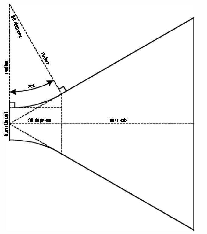
Good question.
Here is a sketch from the Hughes paper. It shows that the horn throat radius (arc) should be tangent to the horn surface and normal to the driver exit. There is only one unique radius that satisfies those conditions in any plane drawn through the horn central axis.
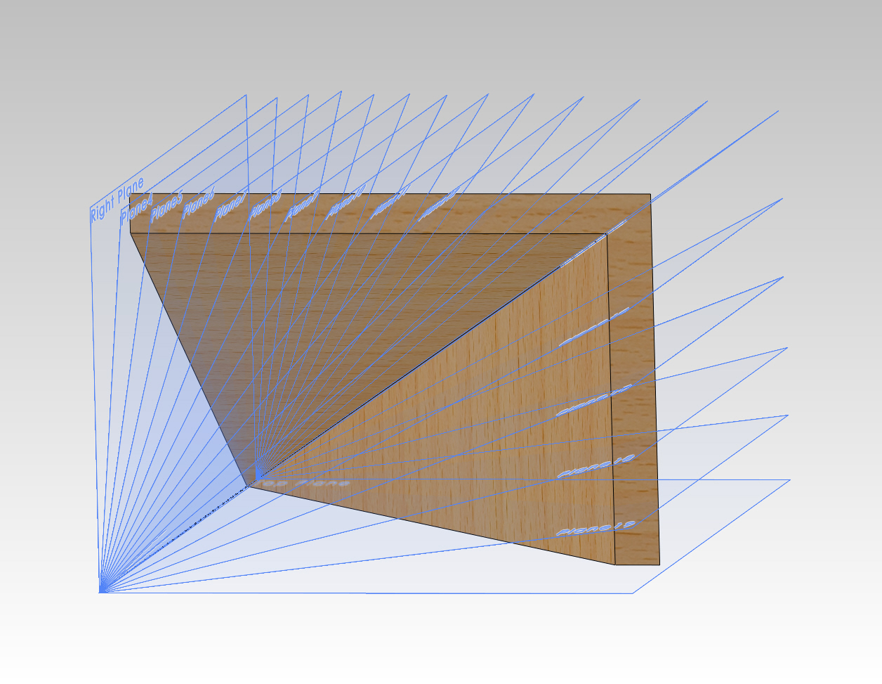
Here is a set of construction planes drawn through the horn central axis. I only used 1/4 of the horn to take advantage of symmetry.
Working in each plane I constructed the "arcs" shown in the Hughes sketch. I matched the compression driver exit angle (7 degrees single sided). I also located the horn apex 10 mm into the driver throat to get the driver closer to the midrange ports. The ports can not move further into the horn. There must be sufficient horn area where they are located to not interfere with the compression driver output.
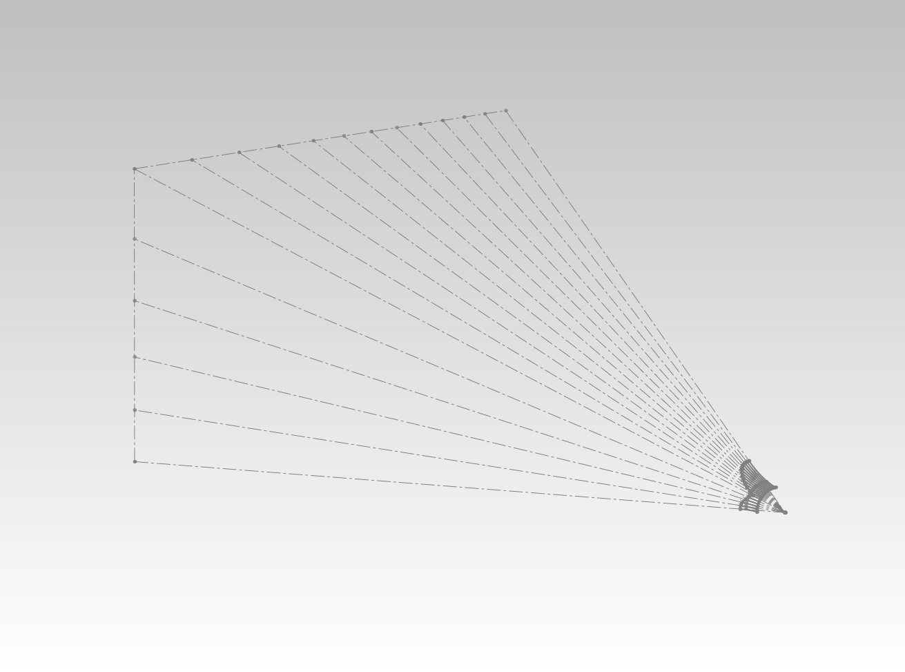
Here you can see more detail. The short construction lines match the driver exit angle. In each construction plane only one "arc" fits that is tangent to the horn and normal to the driver exit cone.
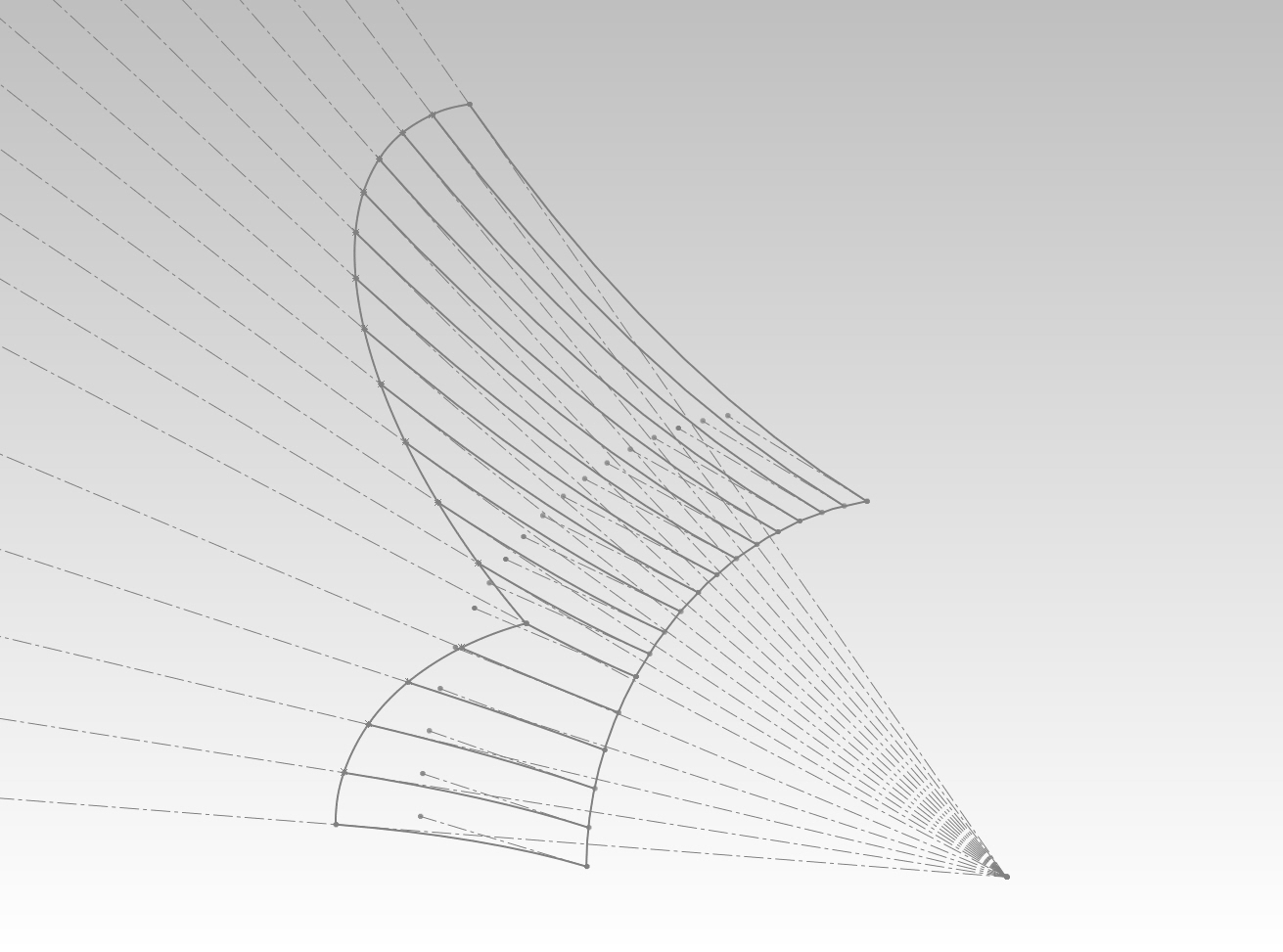
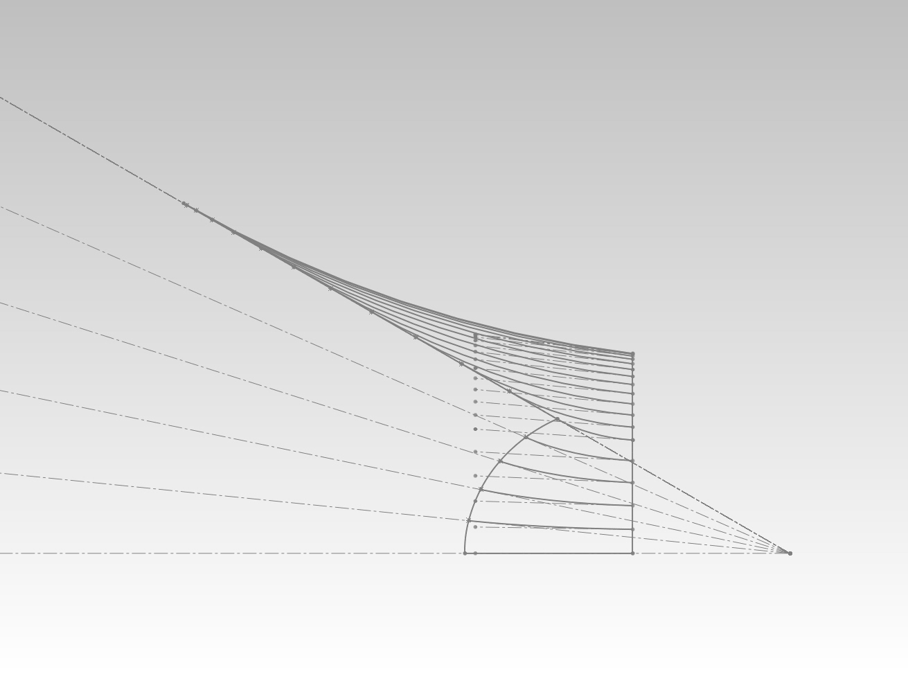
After lofting the surfaces along the "Hughes arcs" this is what results:
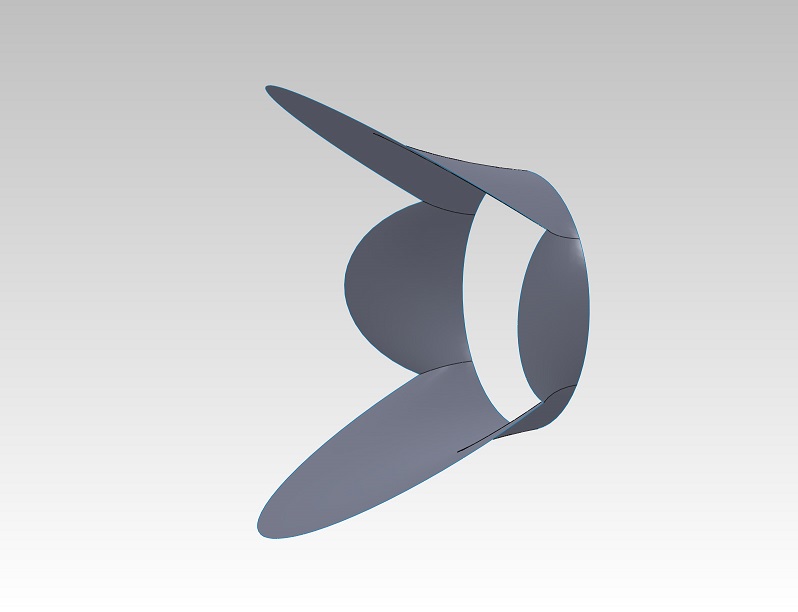
One can use a CD with a short factory made square horn that has the nice radius at the throat already. Then build the flat horn panels as extensions from this optimized short horn. You just need to make sure the transition from the factory square horn to the synergy be smooth. These horns are typically 90 deg or 60 deg square and have a nice 4 bolt flange that lets them be mounted to the back of the synergy horn.
Chrapladm,
I started to work on it and found that the horn really gives a high gain to the mids and the bass is relatively weak and can't be made to be the same level. It will require a resistor and inductor to flatten the response. The Qts is fairly low thus the bass extension is not very deep. I was trying to optimize the port location to flatten it out. I will post what I have as soon as I get to a computer.
I started to work on it and found that the horn really gives a high gain to the mids and the bass is relatively weak and can't be made to be the same level. It will require a resistor and inductor to flatten the response. The Qts is fairly low thus the bass extension is not very deep. I was trying to optimize the port location to flatten it out. I will post what I have as soon as I get to a computer.
- Home
- Loudspeakers
- Multi-Way
- Suitable midrange cone, for bandpass mid in Unity horn.