I take it the DE120 likes to be crossed at or around 1400hz?
I was getting ready to order the M10's for my SH attempt.
In a domestic setting it can be crossed as low as 850Hz.
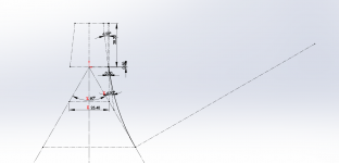
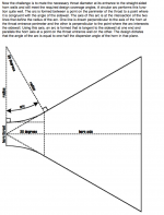
In trial fitting a bunch of different mids on my horn drawing this weekend I realized that with the 90 degree horn, I can actually get the mid holes closer to the apex than with a 60 degree horn because the 90 degree horn walls take longer to move a given perpendicular distance down the throat from the apex.
Comparing notes:
I figured I could get the Misco RDC3T holes within .672" of the physical apex. With a .25" mounting plate, I get the 1/4 lambda null at 1774 hz with the DE120. However, if I go DE250 and its path length is indeed 37mm, then I have the null at 1421 Hz. The benefit though is its closer to the recommended crossover. The BMS4550 comes in at 950 and is above its recommended minimum but I wonder if the close-in mid holes for it won't compromise the high end ...
I am admittedly a sloppy builder.
But after building a number of Unity horns, I generally just 'eyeballed' the location of the mid-range holes.
There's so many variables here, it's really hard to assume that the 1/4 wave reflection is going to happen exactly where you expect it to happen.
Stuffing the compression driver with reticulated foam should also reduce the effect of that reflection, by basically making the path resistive.
I draw precisely in Sketchup hoping some of that precision will transfer to the wood ")
From what I've heard here, the physical path length is a worst case. I know there is going to be a lot of cut and try. I just want to be in the ball park to begin with. Thanks for the idea about the foam.
From what I've heard here, the physical path length is a worst case. I know there is going to be a lot of cut and try. I just want to be in the ball park to begin with. Thanks for the idea about the foam.
"Stuffing the compression driver with reticulated foam should also reduce the effect of that reflection, by basically making the path resistive."
Patrick/John: Do you have any idea how many db of attenuation per inch at 1 KHz or so can be achieved this way?
Thanks,
Jack
Patrick/John: Do you have any idea how many db of attenuation per inch at 1 KHz or so can be achieved this way?
Thanks,
Jack
Why are you using a resonant cavity to delay the mids, rather than a dsp?
Would you get more bandwidth by plugging them like compression drivers?
Patrick often complains how difficult to get mids to play high enough.
I don't understand what you're asking here.
"Stuffing the compression driver with reticulated foam should also reduce the effect of that reflection, by basically making the path resistive."
Patrick/John: Do you have any idea how many db of attenuation per inch at 1 KHz or so can be achieved this way?
Thanks,
Jack
That's a question for Dr. Geddes.
Its answered in the Geddes thread. I found a foam/no foam FR trace with a 2db difference for a "geddes style"waveguide between 1 and 5khz at about page 527 in the geddes on waveguides thread. attenuation gradually increased to about 4 db at 16 KHz. That isn't enough to kill the reflection.
Good question.
Here is a sketch from the Hughes paper. It shows that the horn throat radius (arc) should be tangent to the horn surface and normal to the driver exit. There is only one unique radius that satisfies those conditions in any plane drawn through the horn central axis.
(...)
Here´s my take on it:
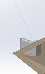
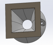
First draw the curves on two sketches. Only top sketch shown here. An equal sketch from the left is also drawn. The bit at the top is a rough guess at the CD exit.
The horn is drawn all the way back (it was simpler that way) and the two curves (from top and left perspective) are lofted to make a quadrant of the externals of the adapter.
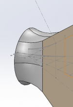
The loft is mirrored on both axis.
Now make a quadrant of the internal lofted cut:
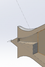
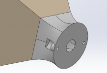
And mirror those twice, add screw holes, remove horn stub etc.
With compression driver dummy model mounted
Attachments
How about adding a phase plug to the throat like some JBLs etc. It would be relatively easy do make these with 3D printers
Here is a nice story about some experiments Phase Plugs
Here is a nice story about some experiments Phase Plugs
(Warning: Take this with a grain of salt, as I´m sure the experts will chime in with the true answer, and I don´t know much about horn design or phaseplugs): As far as I understand, the DE250 (as I was thinking to use) has a phase plug already and has a conical expansion at 13 degrees. The shape of the waves should then be suitable to continue a 13 degree expansion, or, as in the adapter here, transform the waves into a 60 degree expansion. I would think that printed phase plugs could be more useful if mating a woofer to a horn than a CD like this.
Would be nice if somebody with more knowledge could confirm/correct this.
Would be nice if somebody with more knowledge could confirm/correct this.
Yep, the phase plug must match the driver and horn, the frequency range etc.
But my brains flashed with this concept of a throat adapter section 3D modelling and 3D printing. This is very versatile and offers great opprotunities for prototyping and making several versions and modifications.
But my brains flashed with this concept of a throat adapter section 3D modelling and 3D printing. This is very versatile and offers great opprotunities for prototyping and making several versions and modifications.
Its answered in the Geddes thread. I found a foam/no foam FR trace with a 2db difference for a "geddes style"waveguide between 1 and 5khz at about page 527 in the geddes on waveguides thread. attenuation gradually increased to about 4 db at 16 KHz. That isn't enough to kill the reflection.
The foam acts as an acoustic filter, similar to the use of fiberglass batting. Foam is used because its effect is consistent, whereas fiberglass density is variable.
In the Homster thread I saw that the effect is greater with less than perfect horns. About 10dB iirc.
Here's why this happens:
The profile of the Geddes waveguide is explicitly designed to minimize diffraction and reflection. Due to that, the effect of the foam is subtle.
In a Homster, the wave goes through the foam multiple times. For instance, the output of the midranges in a Synergy horn will go through the foam in the throat a minimum of two times. (From midrange tap to throat, then back out again like a ping pong ball). So that's how u end up with attenuation that can exceed six decibels.
Foam in the midrange taps is particularly useful because Synergy horns have midrange power to burn. If anything, it's the compression driver that's the weak link in a Synergy.
Besides all that, early reflections just sound like ****. They're a great way to ruin an otherwise good loudspeaker.
I've definitely wondered if some of the horn honk in my own Unity projects was due to HOMs
Hi Patrick:
I momentarily played with the idea of using enough foam to reduce the reflection to the point where it could be ignored. Suppose one could get a flat 6db attenuation per pass. The forward wave from the CD would lose 6 db. the reflection would pass through twice and lose 12 db. If I didn't screw up my math, the null would be only 3 db, bordering inaudibility. The BMS4550 has enough gain and sensitivity to give up 6db for home use, so maybe the idea could be made to work with the right material. Might be fun to try but no doubt easier to get a CD with a shorter path length and not have to have the mid-holes so close to the throat of the horn. Sure, foaming the horn for HOMs is a good idea regardless.
I momentarily played with the idea of using enough foam to reduce the reflection to the point where it could be ignored. Suppose one could get a flat 6db attenuation per pass. The forward wave from the CD would lose 6 db. the reflection would pass through twice and lose 12 db. If I didn't screw up my math, the null would be only 3 db, bordering inaudibility. The BMS4550 has enough gain and sensitivity to give up 6db for home use, so maybe the idea could be made to work with the right material. Might be fun to try but no doubt easier to get a CD with a shorter path length and not have to have the mid-holes so close to the throat of the horn. Sure, foaming the horn for HOMs is a good idea regardless.
Any frequencies of a wavelength larger than the phase plug slits (that is any audible frequencies) will diffract outward and will "fill" a horn up to around 90 degrees.As far as I understand, the DE250 (as I was thinking to use) has a phase plug already and has a conical expansion at 13 degrees. The shape of the waves should then be suitable to continue a 13 degree expansion, or, as in the adapter here, transform the waves into a 60 degree expansion.
The 13 degree exit angle should be faired in to the desired throat angle to avoid an abrupt change in angle and HF diffraction problems.
The smoothed transition does not require a separate throat adapter.
Attachments
Bill:
DSP correction is a given. Nevertheless, if you have >= 6db loss at 1-5 KHz, you'll likely have twice that at 16 kHz, which already needs 6 db shelf filter boost. After all that, even the mightiest CD is likely to show some sign of strain at the high end. That is why I nixed it early. The temptation to get the mid holes further down the horn so they don't affect the high end is strong but at least several (you among them) have shown its not necessary. Now the woofer holes in your design did have an impact - which suggests crossing to an external woofer/subwoofer >100 hz might help.
DSP correction is a given. Nevertheless, if you have >= 6db loss at 1-5 KHz, you'll likely have twice that at 16 kHz, which already needs 6 db shelf filter boost. After all that, even the mightiest CD is likely to show some sign of strain at the high end. That is why I nixed it early. The temptation to get the mid holes further down the horn so they don't affect the high end is strong but at least several (you among them) have shown its not necessary. Now the woofer holes in your design did have an impact - which suggests crossing to an external woofer/subwoofer >100 hz might help.
Any frequencies of a wavelength larger than the phase plug slits (that is any audible frequencies) will diffract outward and will "fill" a horn up to around 90 degrees.
The 13 degree exit angle should be faired in to the desired throat angle to avoid an abrupt change in angle and HF diffraction problems.
The smoothed transition does not require a separate throat adapter.
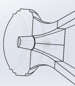
I believe this is what i'm doing with the adapter. Its based on the paper you attach. So rather than building a horn that enda with a square 0.7inx0.7in, i have one that ends at a few cm square. The adapter completes the horn, in a smooth way, ending at a 13 degree angle, and an entry of one inch (circular). I dont claim that its better than smoothing the transition via wood putty or other means. (i will let the experts argue about acoustic merits)
I showed my variant because its a different interpretation of how to implement the hughes adapter than hulkss showed, and would like comments on whether it looks correct based on how others in the forum read the paper.
EDIT: I should add - it´s also fun to get something 3d printed, so that´s one of the motivations for drawing it up like this.
And: Thank you - interesting about the diffraction filling the horn.
Last edited:
The extra thickness of the adapter is trouble for the mid driver's offset entry location and depth.I believe this is what i'm doing with the adapter. Its based on the paper you attach. So rather than building a horn that enda with a square 0.7inx0.7in, i have one that ends at a few cm square. The adapter completes the horn, in a smooth way, ending at a 13 degree angle, and an entry of one inch (circular).
Other than that detail, no problem
.- Home
- Loudspeakers
- Multi-Way
- Suitable midrange cone, for bandpass mid in Unity horn.