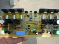
Matching transistor
check all BC transistor maybe the hFE too much differences...
Today I changed all BC550B & BC560B to higher hFE BC550C & BC560C.
They are closely matched so DC offset should be zero
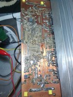
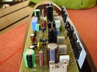
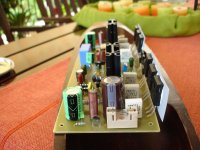
I'm cleaning the PCB just now but it is just too clean
Hi Mr. Arif Budiyanto...Dear Mr. Mile S...
thank you so much for your kind advise as always...
I will check my amp again...before it is fine only zobel network was hot when playing couple songs...
Strange behavior is, when first turn on, the dc offset is high, 300mv and more, and getting down after more or less 10 minutes up to 14 mV...
the sound is Ok...really like this amp...
check all BC transistor maybe the hFE too much differences...
Today I changed all BC550B & BC560B to higher hFE BC550C & BC560C.
They are closely matched so DC offset should be zero
I'm cleaning the PCB just now but it is just too clean
Attachments
Ok, Bli John...
After checked last night, I found that one of bc transistor was not soldered properly, soon after fixed it, dc offset measured 44 mV, after about 5minutes turned on then dc offset went to 24mV...my SR200 has 20pf cap...
I did matched all bcs and 5401...I am pretty happy with my SR200 so far, while waiting for my health becoming recovered. I will explore my SR200 again later...
Thank you Mr. Mile Slavkovic for sharing SR200 design..
Best Regards.
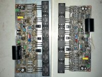
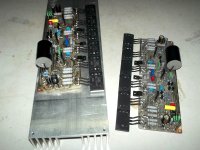
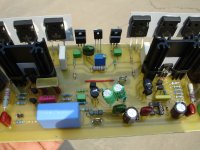
studio reference
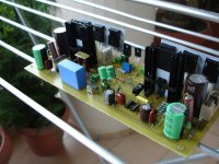
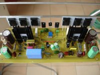
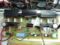
Just after first test!
+-/45V rail
150mA idle current
+1mV offset without servo.
And now the journey starts again.
Just after first test!
+-/45V rail
150mA idle current
+1mV offset without servo.
Attachments
Last edited:

Just after first test!
+-/45V rail
150mA idle current
+1mV offset without servo.
Nice work,
Regards
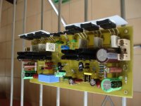
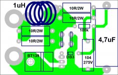
PSU & Speaker terminal
Hi all
SR200 now need speaker terminal, they are tested
2 x 300VA 50VAC each transformer, 2 bridge diode & 4 x 10000uF per rail.
to Mr Mile
I'm planing to build a single transformer 600VA but
2 x 50VAC for stereo or
4 x 50VAC for dual mono,
which one is better?
Please check this speaker terminal too, is this OK?
Regards
Attachments
studio reference
What about stability of your unit?
Have you add compansation capacitor( 18pf )between collector Q9 ,base Q2 or
it wasn't necessary.
I'm afraid that stability of this amplifier varies from one to next and i don't know why this happens.
I would be grateful if we had a reply from the designer about this topic and the appropriately addresses
Hi friendHi all
SR200 now need speaker terminal, they are tested
2 x 300VA 50VAC each transformer, 2 bridge diode & 4 x 10000uF per rail.
to Mr Mile
I'm planing to build a single transformer 600VA but
2 x 50VAC for stereo or
4 x 50VAC for dual mono,
which one is better?
Please check this speaker terminal too, is this OK?
Regards
What about stability of your unit?
Have you add compansation capacitor( 18pf )between collector Q9 ,base Q2 or
it wasn't necessary.
I'm afraid that stability of this amplifier varies from one to next and i don't know why this happens.
I would be grateful if we had a reply from the designer about this topic and the appropriately addresses
Last edited:
studio reference
My new unit comes unstable when external zobel added (without any load)
V=34v on 100R instead of fuse.
When external zobel is absent and the load also ,V=15v on 100R.(normal condition).
That happens without compansation capacitor(18pf).
It's usefull to see what happens with zobel on board.
I can test this soon .
Hi friend
What about stability of your unit?
Have you add compansation capacitor( 18pf )between collector Q9 ,base Q2 or
it wasn't necessary.
I'm afraid that stability of this amplifier varies from one to next and i don't know why this happens.
I would be grateful if we had a reply from the designer about this topic and the appropriately addresses
My new unit comes unstable when external zobel added (without any load)
V=34v on 100R instead of fuse.
When external zobel is absent and the load also ,V=15v on 100R.(normal condition).
That happens without compansation capacitor(18pf).
It's usefull to see what happens with zobel on board.
I can test this soon .
Last edited:
The R+C Output Zobel must be from output devices to Power Ground via a short, low inductance route.
The L//R part can be anywhere between the amplifier output and the chassis mounted speaker terminals.
I prefer it located in the cable between amp and terminals.
If a Pi version is being used then the second R+C should be across the speaker terminals.
The amplifier output devices MUST see the Output Zobel by a low impedance route.
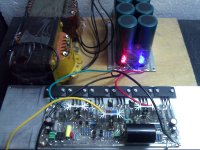
studio reference
Now the zobel is on mainboard .
Repeating tests with 10R resistors instead of fuses.
V=1.5V on 10R.(idle150mV/RAIL)
Testing the board with 100R isn't the right way at all.
The capasitor 18pf is connected, because oscillograms show the same results as in the previous board.
After this it's time for music!
Soon on youtube with the new unit.
Mr Adrew thanks for reply.I would like to listen to your opinion about servo.Do you prefer servo or not?
Mr Mile ....just studio sound ,with common parts only!
Congratulations!
Regards.
My new unit comes unstable when external zobel added (without any load)
V=34v on 100R instead of fuse.
When external zobel is absent and the load also ,V=15v on 100R.(normal condition).
That happens without compansation capacitor(18pf).
It's usefull to see what happens with zobel on board.
I can test this soon .
Now the zobel is on mainboard .
Repeating tests with 10R resistors instead of fuses.
V=1.5V on 10R.(idle150mV/RAIL)
Testing the board with 100R isn't the right way at all.
The capasitor 18pf is connected, because oscillograms show the same results as in the previous board.
After this it's time for music!
Soon on youtube with the new unit.
Mr Adrew thanks for reply.I would like to listen to your opinion about servo.Do you prefer servo or not?
Mr Mile ....just studio sound ,with common parts only!
Congratulations!
Regards.
Attachments
Last edited:
Hi Thim,Hi friend
What about stability of your unit?
Have you add compansation capacitor( 18pf )between collector Q9 ,base Q2 or
it wasn't necessary.
I'm afraid that stability of this amplifier varies from one to next and i don't know why this happens.
I would be grateful if we had a reply from the designer about this topic and the appropriately addresses
I try without 18pF and the result resistor on zobel get quite hot... you know why
Then I add 22pF(this what I have) at collector Q9 to base Q2, now that resistor is cold...
I guess this cap maybe necessary if the heatsink on 3 MJE's is not grounded...
Thimios, do your little heat sink grounded?
I can't grounded it so 22pF or maybe 18pF is the best I can do with my PCB
because the error when I made this PCB all parts is on the copper side
Ok, we waiting what Mr Mile says about it...
Regards
studio reference
The problem is independent of transistors grounding.
My first unit haven't heatsink grounding.
Second have these heatsink grounding.
Same problem on first and second.
Hi Thim,
I try without 18pF and the result resistor on zobel get quite hot... you know why
Then I add 22pF(this what I have) at collector Q9 to base Q2, now that resistor is cold...
I guess this cap maybe necessary if the heatsink on 3 MJE's is not grounded...
Thimios, do your little heat sink grounded?
I can't grounded it so 22pF or maybe 18pF is the best I can do with my PCB
because the error when I made this PCB all parts is on the copper side
Ok, we waiting what Mr Mile says about it...
Regards
The problem is independent of transistors grounding.
My first unit haven't heatsink grounding.
Second have these heatsink grounding.
Same problem on first and second.
studio reference
Hi Mr Mile.
Please tell us which is the recommended pcb for the sr200 amplifier.
Regards.
Stability depend of pcb design.
Hi Mr Mile.
Please tell us which is the recommended pcb for the sr200 amplifier.
Regards.
Last edited:
Hi Mr Mile.
Please tell us which is the recommended pcb for the sr200 amplifier.
Regards.
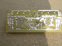
You can use all pcb designs by 'alex mm' just add extra compensation. You can see extra caps for compensation on many brand amps placed on botom side of pcb.
Regards
You can use all pcb designs by 'alex mm' just add extra compensation. You can see extra caps for compensation on many brand amps placed on botom side of pcb.
Regards
It's usefull to give us more details.
We must add compensation capacitors, but where?
Any other recommended compensation capacitors except the one between collector Q9 base Q2?
Regards.
Last edited:
Ok, so we must try our PCB & see if it is stable or not... that is DIY spiritStability depend of pcb design.
maybe I will try designing PCB again next time,
for now this one is enough & the power is more than enough
Yes, I saw this sometimes... so that is why I see cap or caps on bottom sideYou can use all pcb designs by 'alex mm' just add extra compensation. You can see extra caps for compensation on many brand amps placed on botom side of pcb.
Regards
Thim, that is the only way to tame oscillation that work very well, now I'm enjoying the sound of SR200... Don't try another things, that compensation is from the designer guide. He know what is the best to do with this amp...It's usefull to give us more details.
We must add compensation capacitors, but where?
Any other recommended compensation capacitors except the one between collector Q9 base Q2?
Regards.
Now both SR200 I've build bias with 17mV at RE 0,34 ohm (2 x 0,68 ohm that I use)...
after adjust bias now :
Deep bass that I'm looking for is there


bonus with clear high, noise free, dead silent when vol is minimum & very great music when playing
Oh, why I don't finish it earlier
(the PCB is from last year) Apexaudio / Mr Mile thanks for sharing this SR200, & for guide us how to make it stable.
Will build better PSU next time & of course waiting another new amplifier from Apexaudio
Best Regards
Ok, so we must try our PCB & see if it is stable or not... that is DIY spirit
maybe I will try designing PCB again next time,
for now this one is enough & the power is more than enough
Yes, I saw this sometimes... so that is why I see cap or caps on bottom side
Thim, that is the only way to tame oscillation that work very well, now I'm enjoying the sound of SR200... Don't try another things, that compensation is from the designer guide. He know what is the best to do with this amp...
Now both SR200 I've build bias with 17mV at RE 0,34 ohm (2 x 0,68 ohm that I use)...
after adjust bias now :
Deep bass that I'm looking for is there
bonus with clear high, noise free, dead silent when vol is minimum & very great music when playing
Oh, why I don't finish it earlier
Apexaudio / Mr Mile thanks for sharing this SR200, & for guide us how to make it stable.
Will build better PSU next time & of course waiting another new amplifier from Apexaudio
Best Regards
I am preparing several new projects in all series and one new series of high definition amplifiers. HD200 should outweigh the SR200 features and I hope in the sound.
Regards
I am preparing several new projects in all series and one new series of high definition amplifiers. HD200 should outweigh the SR200 features and I hope in the sound.
Regards
.....Thats Good news Mr. Mile
Thanks and will wait for that.
- Home
- Amplifiers
- Solid State
- Studio Reference Amplifier