Sanken for SR200
And this is 3 pairs Sankens that I want to use they look great
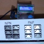
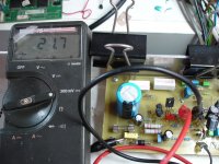
kang Naf do you know what the meter says...
B=beta Uf=...?
No... I will make ordinary but hand made EI trafo spesial for it, no SMPS for now.@Bli John... i know what you prepare for supply
And this is 3 pairs Sankens that I want to use
they look greatkang Naf do you know what the meter says...
B=beta Uf=...?
Attachments
Last edited:
Witch value R11 is on your circuit?No... I will make ordinary but hand made EI trafo spesial for it, no SMPS for now.
And this is 3 pairs Sankens that I want to use
kang Naf do you know what the meter says...
B=beta Uf=...?
Hi my friend, you got PM...Witch value R11 is on your circuit?
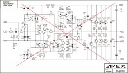
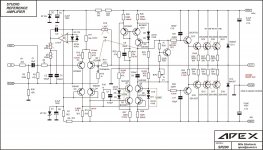
R11 on my circuit is 15k, & all part just like in this schematic:
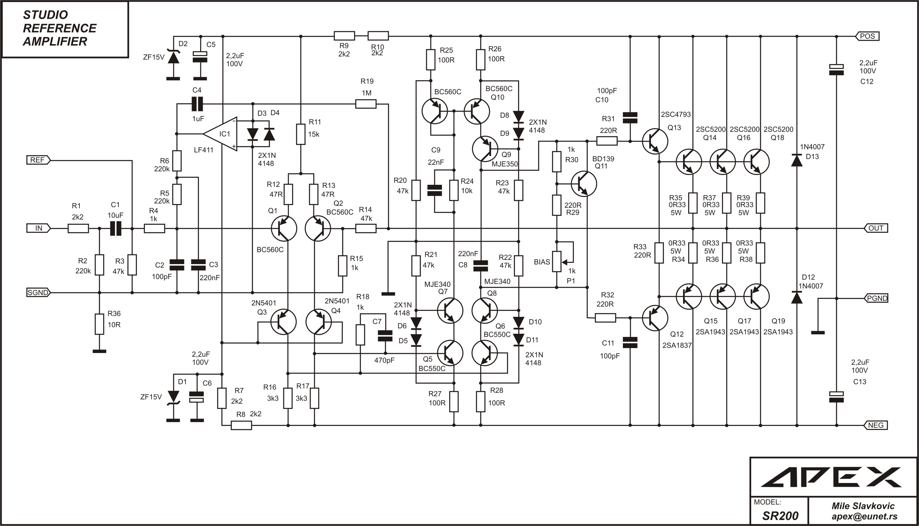
To Mr. Mile ...
may I change input transistor to 2SK170 ?
(have been mentioned in old post but no one make it)
If can, please tell us what need to be changed...
Regards
Last edited:
sr200 studio refer.
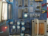
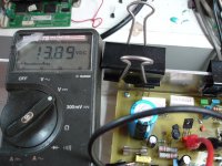
Look at this.
I use this Elektor published curve tracer.
Keep in mind that with all theese circuits you can match small signal transistors only.
It's not recommented to match power transistors with that's circuits.
For power transistors matching you need high current and high voltage devises.
I see circuits like this in Elektor but i haven't made something like this yet.
Thanks my friend.Hi my friend, you got PM...
R11 on my circuit is 15k, & all part just like in this schematic:
To Mr. Mile ...
may I change input transistor to 2SK170 ?
(have been mentioned in old post but no one make it)
If can, please tell us what need to be changed...
Regards
Look at this.
I use this Elektor published curve tracer.
Keep in mind that with all theese circuits you can match small signal transistors only.
It's not recommented to match power transistors with that's circuits.
For power transistors matching you need high current and high voltage devises.
I see circuits like this in Elektor but i haven't made something like this yet.
Attachments
Last edited:
59.6V on R14 .... This value is with or without servo?I check again my SR200, now in cold heatsink... DC offset is 0,..mV
V base Q2 to ground = 63mV
V on R14 = 59,6mV
check this http://www.diyaudio.com/forums/solid-state/173462-studio-reference-amplifier-77.html
that because not grounded heatsink & missing cap...
Thimios, do you use small heat sink for all MJE transistor & grounded the heat sink?
they are warm(maybe hot) on +/-45VDC
Hi Mr Mile,
I want to know the inductor value (in uH) & what happen when we increase or decrease the value?
because I got smoke on resistor zobel today (resistor series with 100nF to ground).
I use speaker terminal that was use on AX14, maybe because of that?
The resistor smoked when I unplug the speakers & with "loop" cable from input to ground.
63mV bace to ground Q2 is with or without servo?
Hi Mr Adrew R33=220RThim,
R33 (220r) in post1323 sets the driver bias current. This will make the drivers run warm.
What resistor value and what voltage do you have across R33 in your builds?
This time haven't circuit diagramme on my hands (where i has write some measurments) i come back in a few minutes.
Thanks for all.
V R33=1.2V
Last edited:
sr200 studio refer.
Dit you believe that raising power supply voltage affect the offset ?
O no just now i remember that asymmetric presents with servo also even if offset is zero.
That seems normal.
~5mA will be warm.
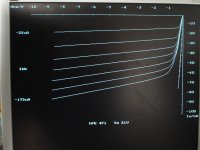
Where does 5mA put the transistor in it's typical hFEvsIc & fTvsIc?
Maybe the drivers are too far away from optimum Ic to operate as fast drivers.
Dit you believe that raising power supply voltage affect the offset ?
O no just now i remember that asymmetric presents with servo also even if offset is zero.
Last edited:

Hi brother!! sorry my mistake...wrong written, I mean 10pf not 20pf...Hi mas Arif,
connecting in series your 20pf, you have 10pf
I have some of 10pf caps but no 20pf caps. It is stated that 18 pf cap should put in the amp as compensation cap. So, which is the best practice? install 10 or 20 pf...if 20pf is the best I will put 2 X 10pf in parallel...
Thank you.
Best Regards...
Apex,
could you make a designer's comment on my post 1330?
Could a very low driver bias current make the amplifier susceptible to component variations?
Could two apparently identical builds end up behaving differently due to the transistor parameters being sufficiently different?
could you make a designer's comment on my post 1330?
Could a very low driver bias current make the amplifier susceptible to component variations?
Could two apparently identical builds end up behaving differently due to the transistor parameters being sufficiently different?
Apex,
could you make a designer's comment on my post 1330?
Could a very low driver bias current make the amplifier susceptible to component variations?
Could two apparently identical builds end up behaving differently due to the transistor parameters being sufficiently different?
This is the reason why the design was changed to a triple emitter follower for SR800
Hi Mr. Mile,This is the reason why the design was changed to a triple emitter follower for SR800
SR800 is not for share, but can we optimize this SR200?
Can I changed the resistor that AndrewT said not optimal...
I want more driver current for feeding the Sanken's(100mA bias or more)
What need to be changed please help
sr200 studio refer.
Everything starts from here.
This modification is the cause of the problem.
Today early in the morning about 5.30 o'clock i examined the amplifier again.
But this time I was sure for the pcb because it passed the point to point test.
As changing transistors and matchig didn't solve the problem, having in mind that the others' amplifiers didn't have the problem,i decided to return to the original circuit.
So i put at R11 the original value 15K.and that was all!
Thanks everyone for trying to help .
Especialy thanks Mr AdrewT who advised me to stabilize the LTP without servo.
Thanks a lot to John Balli for your instant reply in mine request for measurments.
Last but not least thanks overall feedback for his atempt to help.
Thanks again Mr.Mile for this excellent amplifier.
I also attach this hopping that it will be useful
Replace R11 with 8k2 instead 15k.
Regards
Everything starts from here.
This modification is the cause of the problem.
Today early in the morning about 5.30 o'clock i examined the amplifier again.
But this time I was sure for the pcb because it passed the point to point test.
As changing transistors and matchig didn't solve the problem, having in mind that the others' amplifiers didn't have the problem,i decided to return to the original circuit.
So i put at R11 the original value 15K.and that was all!
Thanks everyone for trying to help .
Especialy thanks Mr AdrewT who advised me to stabilize the LTP without servo.
Thanks a lot to John Balli for your instant reply in mine request for measurments.
Last but not least thanks overall feedback for his atempt to help.
Thanks again Mr.Mile for this excellent amplifier.
I also attach this hopping that it will be useful
Attachments
Last edited:
Connect 5-10pF from colector Q9 (MJE350) to base Q2 (BC560) for compensation.
My post #769 from 28th July 2012
18pf is always on the board as you request for it.My post #769 from 28th July 2012
Last edited:
18pf is always on the board as you reqest for it.
Replace R7,8,9,10 with 1k instead 2k2, voltage on zeners must be about 15V
Regards
- Home
- Amplifiers
- Solid State
- Studio Reference Amplifier