Attachments
sr200 studio refer.
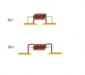
These circuits show a parallel connection of zobel and loundspeaker.
In this case this is an intuctance dummy load,not a zobel.
I can't understand nothing.Here it is.
These circuits show a parallel connection of zobel and loundspeaker.
In this case this is an intuctance dummy load,not a zobel.
Last edited:
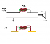
zobel
zobel connection.mine have always looked like this
ok, thanks
Attachments
Last edited:
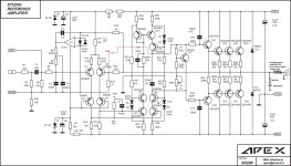
Thank you.Dear Adrew this is shematic last modified by Apex. Red values are the modifications.
Keep in mind that original schematic is functional also with a little problem an overshot
probably.
just 3 changes !
The HF decoupling is not shown.
The MF decoupling is far too low in value.
The Thiele Network on the output is not shown.
Thi,
what are the currents through R12 & 13 and through R27 & 28?
900uA and 25mA per resistor with 8k2 or 500uA and 10mA with 15k value of R11.
sr200 studio refer.
I hopr this help.Thank you.
just 3 changes !
The HF decoupling is not shown.
The MF decoupling is far too low in value.
The Thiele Network on the output is not shown.
Attachments
")
I hopr this help.
Hello Thimios how tall your network inductance Zovel.
See post#1184.Hello Thimios how tall your network inductance Zovel.
sr200 studio refer.
I can measure the currents in the afternoon.
Regards.
Oh sorry .Thi,
Apex gave me the theoretical currents. What are your actual currents?
I can measure the currents in the afternoon.
Regards.
Last edited:
Oh sorry .
I can measure the currents in the afternoon.
Regards.
Measure voltages on resistor and calculate currents (I=U/R)
Thimios, if the resistor is soldered with its leads mostly clipped off, then it should have minimal series inductance. That is one example. With your resistor being the core material of the inductor, I don't know how this affects inductor behavior for better or worse. I wouldn't expect a film resistor to do much unless it stuck to a magnet, but I really don't know anything about magnetics.
My response was to the post I quoted, where the resistor leads were left long and soldered at the ends. This would be okay, if the connections to the L/R were right across the resistor rather then inches apart.
My response was to the post I quoted, where the resistor leads were left long and soldered at the ends. This would be okay, if the connections to the L/R were right across the resistor rather then inches apart.
sr200 studio refer.
of course Sr.Measure voltages on resistor and calculate currents (I=U/R)
sr200 studio refer.
V across R13=54mV. I=1.14mA
V across R27=1.042V I=10.4mA
V across R28=974mv I=9.74mA
V across R12=24mV. I=0.5mAThi,
what are the currents through R12 & 13 and through R27 & 28?
V across R13=54mV. I=1.14mA
V across R27=1.042V I=10.4mA
V across R28=974mv I=9.74mA
Thi,
you need to sort the LTP balance first.
Change the Tail current until the Vdrop on the LTP emitters is identical.
Then remeasure the R27 & 28 voltages/currents.
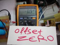
Also check the output offset.
Hi Adrew
output offset is zero.(servo presence)
''Change the Tail current until the Vdrop on the LTP emitters is identical.''
probably you mean closer matched transistors.
It's in my mind to do this.
It is just a prototype for functionality check.
In any cases this is the proof that it is not enough matching hfe
Thanks for your interest
Best regards
Attachments
Last edited:
- Home
- Amplifiers
- Solid State
- Studio Reference Amplifier