Listening To
Here I sit now listening to it. YAY.
It is one channel. My nine pin socket is of poor quality. Very hard to get tube in and moving board( as to get readings from resistors on bottom) loosens tube.
The B+ at R4 is zip nil. At L1 it is 420.
R17 is nil.
T3 is 409, T2 is nil.
Preamp tube 12at7 pins 1 and 6 are 231 and 238. Pins 7 and 8 get static at touching.
V21 pins 3 and 4 are 408 and 409. V11 nil all pins.
I didn't bother with heater pins as all tubes are glowing.
Do have buzz and hum. Should that be taken care of now, or wait until it is in permanent chassis, which went to be powder coated yesterday.
Again thank you.
This is part of the reason I chose Tubelab.
R17 is nil.
T3 is 409, T2 is nil. .....
Check around C2 and make sure the hole for the + capacitor lead of C2 is plated all the way through.
B+ for teminal block 3 comes from the TOP side of the C2 + lead. B+ for terminal block 2 comes from the BOTTOM side of the C2 + lead.
edit: since you have reversed your board, I think, power for your terminal block 2 will be at the TOP of your board, underneath the cap C2. Since you have no B+ at R4, the + lead of C2 where it passes through the board, is almost certainly your problem.
But since you have moved C1 to C2 position, I'm thinking that + hole did not plate through. You seem stingy with solder ....
Win W5JAG
Last edited:
Do have buzz and hum. Should that be taken care of now, or wait until it is in permanent chassis, which went to be powder coated yesterday.
There are multiple causes for hum / buzz. Right now, your heaters are not elevated at DC because of the problem with the + lead of C2 not passing power to both sides of the board. Once that is fixed, the hum / buzz may be gone.
If not, getting the right capacitors in at C1 and C2 will likely fix what is left.
Win W5JAG
I will work on C2.
Playing around, as much as you do around 400+ volts, left end R14, away from U10, shows 417, the other end shows 320. R24 similar,
C11 near R15 shows 4-5 vdc. R17 zip v either end.
V10 pin 1 shows 231 v., isn' that from C2? I probably am wrong, I've done it before here, isn't 't it somewhere between V10 and V11?
Will work on C2.
The + lead of C2 distributes power to both top and bottom sides of the board.
At present, you are only getting power to one side of the board. The side of the board that has the traces for R4 and the terminal block for OPT 2 are not getting power because the + lead of C2 is not connected to them.
The power traces for the CCS for that channel are on the opposite side of the board and are getting power from C2, as is the rest of the board. Fix the C2 pass through and your board will work.
Win W5JAG
I must have overheated C2.
First remelted solder. Solder lowered in height, a bubble came out.
Plugged in amp. Humbuzz a little more pronounced, volume lower. Still one channel.
Reheated C2+, used solder wick trying to remove some solder so heat would go lower.
Music gone. Hum loud. Reading at T1 yellow 346, T3 zip.
I put away for the evening.
Hoping tomorrow is 18 year old day.
The connection between top and bottom of board was lost at cap lead. When replacing caps can a length of wire around the side of board from lead be used?
Seems that would be a way to guarantee connections on both sides of the board.
Just thinkin'.
The better way would be to duplicate the trace.
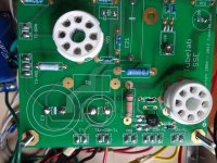
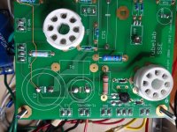
Picture 1 is your board as uploaded by Gcom. If you look closely, you can see the shadow of the trace on the opposite side of the board that is not getting B+.
Picture 2 shows where i have used orange highlight to show the path of the dead trace.
Running an insulated wire from the + terminal of C2 to the pad of R4 nearest the edge of the PCB will bring your dead channel to operation and properly elevate your heaters. if you like, you can use that unused pad for R1 that is connected to C2.
As to your question about capacitors, no one knows if your first cap exploded because it was bad, installed incorrectly, or because your voltage was too high. Likely, it was one of the first two reasons, but, if your voltage was too high, then some remedial measures may be needed.
I would probably order the original values and voltages with wire leads instead of snap caps, and just use C2 to start with so we can see what your B+ comes in at with the choke input configuration. The wire leads will allow you to position the caps with some physical clearance between the cap and the board, to make it easier to get solder on both sides of the board, and re establish the pass through.
My $0.02 USD. Others may have a better idea.
Win W5JAG
Attachments
Last edited:
Personally, until your board is demonstrated to be working in its most basic configuration, i.e triode wired, no cathode feedback, tube rectifier only, I would forget about those *^&* switches.
Look at the grief that rectifier switch being wired backwards caused.
Win W5JAG
Look at the grief that rectifier switch being wired backwards caused.
Win W5JAG
The wire leads will allow you to position the caps with some physical clearance between the cap and the board, to make it easier to get solder on both sides of the board, and re establish the pass through.
My $0.02 USD. Others may have a better idea.
Win W5JAG
This is what I thought would be a better solution for re-establishing the connection between the top and
bottom traces rather than use a piece of insulated wire to duplicate the bottom trace in order to get B+ on both sides ?
Wow, finding the leaded or radial caps is interesting.
I found the 47uF.
For the 120uF can two 56 units in parallel work?
Or?
It looks like 500V capacitors of 100uf and above with wire leads as opposed to the snap in type are hard to find.
Neither DigiKey nor Mouser has them.
You may have to parallel two smaller values to get a value over 100uf. OR you can use the snap in type and use suitable wire leads (say 18awg or 20awg rated for over 500V).
Solder the leads to the snap in lugs of the capacitor and the other ends to the board, which means you will have to strap the capacitor to the inside chassis.
- Home
- More Vendors...
- Tubelab
- SSE first build, caps and other questions.