I thought the Paraline was parabolic due to parallel walls.
At least that is what I calculated.
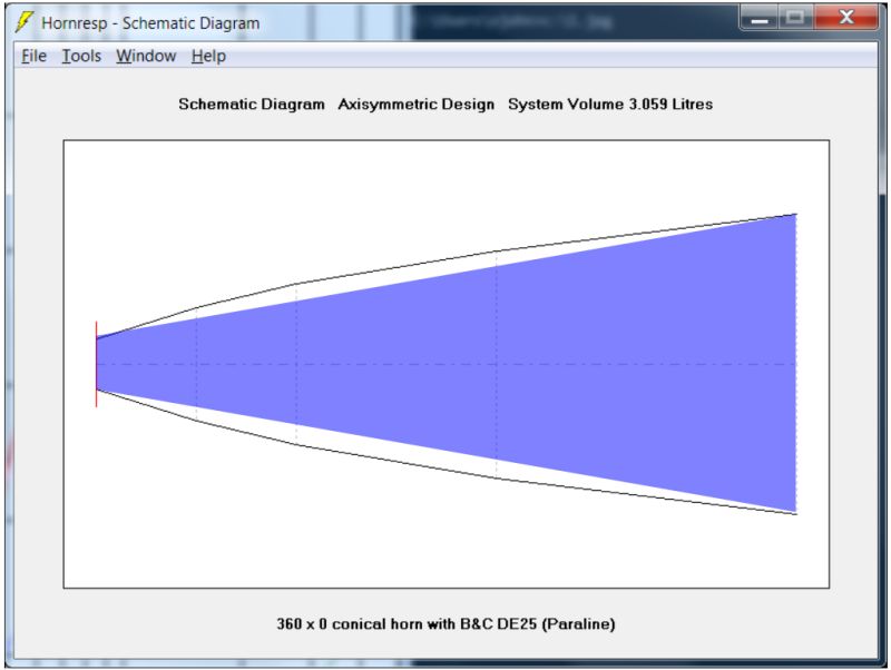
The hornresp sim looks *slightly* parabolic. But hornresp simulates horns as if they're axisymmetric, whereas a radial horn is not.
In the sim above I've overlaid the hornresp prediction for a radial horn, with the wall shape of a narrow angle conical horn.
I think reducing the volume at the throat of the compression driver should improve things; it basically gets the flare rate closer to a proper high frequency horn. (IE, a rapid expansion at the throat, not a gradual one.)
Another though that I had was to mate a very short conical horn to the Paraline, to improve the high frequency loading. (After all, every horn is basically a horn on top of a horn on top of a horn on top of a horn... You can visualize every horn as a series of horns stacked on top of each other.)
So it would go like this:
Conical horn -----> Paraline ---> Conical horn
Basically conical for high frequency , Paraline for midrange loading and directivity change, then conical for low frequency loading.
The thing is, that conical horn might work best inside the actual throat, like a small cone shaped insert right in the throat.
Hi john
I have not read the whole thread, so maybe that's my mistake, but I am having trouble extending the paraline concept - which is an efficient way to make a cheap phase plug for a cone radiator (as I see it on their website) - into something that one would call a "horn". What am I missing?
In a nutshell, what is the concept? Do you just keep layering on the horn in ever expanding flat pancake cross sections?
As far as I can see the area increase in a paraline is linear with distance. Which means a parabolic expansion (if the horn was axisymmetric).
The blue in your diagram would then be incorrect as the area increase is not linear in a conical horn.
The black outline would be more like parabolic expansion which have linear increase in area.
What I noticed is that paraline pretty much always have a slow flare rate compared to length which gives a rather poor loading.
It does give a neat way to convert a point source to a line source though, so I guess you could call it a waveguided phaseplug.
Earl,So it is just a phasing plug? One that has a small depth and easy construction, but still requires a horn?
Why is a small dpeth such a desirable feature? Its not like the phase plug depth is anything remotely comparable to the depth of the horn.
At high frequencies, a Paraline has dispersion (depending on the shape of the "eye") of as little as 0 (or even converging) to perhaps as much as 40 degrees dispersion.
A conical horn with 0 degree high frequency dispersion would have to be infinitely long, and even a 10 degree conical vertical expansion horn would more than double the cabinet depth of the VTC line arrays.
The narrow HF dispersion the Paraline allows with a short depth is a good thing for multiple HF drivers used in a line array (or a single multiple HF driver narrow vertical dispersion Synergy horn),but not desirable for home use, as the HF dispersion expands as it lowers in frequency.
The Paraline is a sort of phasing plug requiring a horn (unless one wants the horizontal output to diffract in an uncontrolled manner) the use of which for home applications is redundant. The construction is not particularly easy to do well, and even when well done results in a more ragged frequency response than a normal conical horn that it usually would be coupled to.
However, the above problems do not seem to keep Patrick from continuing to build and discard them
") .
.Art
So it is just a phasing plug? One that has a small depth and easy construction, but still requires a horn?
Why is a small dpeth such a desirable feature? Its not like the phase plug depth is anything remotely comparable to the depth of the horn.
An externally hosted image should be here but it was not working when we last tested it.
One way to visualize the Paraline is to picture an omnidirectional horn like the Duevel Sirius, but folded over.
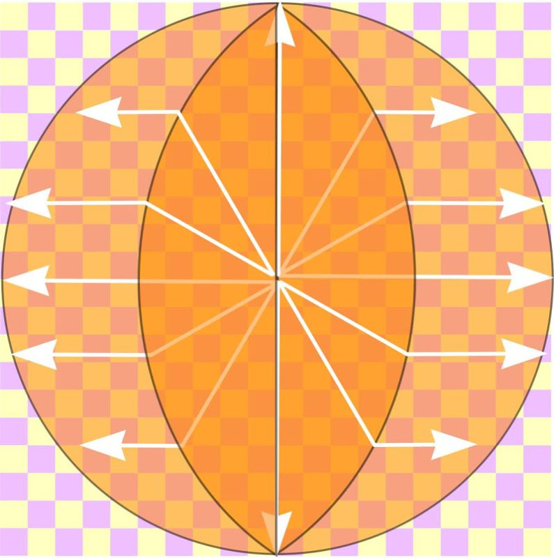
The radial horn is folded in an unusual way; the fold is in the shape of an 'eye'.
Bottom line -
The distance from the origin of the radiator to the exit of the horn is equidistant for two cases:
1) a point
2) a ring
And since Danley uses ring radiators, the Paraline makes a very nice waveguide for the BMS ring radiators.
As for your questions:
1) No, it's not just a phase plug. It's a radial waveguide that's been folded in a unique way. The pathlengths are equidistant for two diaphragm shapes - a point and a ring. Due to this, the output wavefront is in-phase at all points along the waveguide exit.
2) The small depth is a great feature because it would take a much deeper horn to get the same output shape. For instance, if you wanted to get ten degrees of vertical coverage using a conical waveguide with a mouth that's 25cm tall, you would need a waveguide that's 145.16 centimeters deep. (Due to the very narrow coverage, the waveguide ends up being very very deep.)

If you look at the waveguide on devices like the B&C WG7, you'll notice that their depth should be much much deeper to get the narrow coverage necessary to keep the two devices from overlapping with each other. Of course, a very very deep waveguide will have the wrong loading for the low end of the device; a waveguide that's 145.16cm deep is going to load the midrange very poorly. (assuming it's not axisymmentric)
For me personally, the really cool thing about the Paraline isn't the output shape; it's the fact that you can bend the wave. For instance, you can tweak the pathlength and make the sound go to the left or to the right. Or you can create an output wave that's converging or diverging. Check out the CLF measurements of the Danley Genesis horns, and you'll see that it's working.
Is it perfect?
No, not even close. If you look at the CLF data on the SH-50, they're just freakishly well behaved in their polar plots.
BUT
Rooms aren't perfect either, and I don't have the space for a horn that's as deep as my refrigerator. Much less five of them
So it has some insanely cool applications in home theater, car audio, computer sound, pro sound, etc. Basically environments where we don't have room for ginormous waveguides.
Last edited:
The Paraline is a sort of phasing plug requiring a horn (unless one wants the horizontal output to diffract in an uncontrolled manner) the use of which for home applications is redundant. The construction is not particularly easy to do well, and even when well done results in a more ragged frequency response than a normal conical horn that it usually would be coupled to.
However, the above problems do not seem to keep Patrick from continuing to build and discard them
Art
Well keep in mind I don't actually like music, I just like building things, that's why I have a garage full of half finished loudspeakers and bicycles
As for the 'sound' of the Paralines, a lot of them sounded really good; and measured better than I would have ever expected.
Are there wrinkles in the response? You bet!
But the response errors were in spite of the good sound that I was getting, and that's why I stopped building so many, and really started studying them, to figure out WHY they sounded good.
And I think the good and the bad boils down to this:
the bad:
1) When you make a horn too small the response shape devolves into a series of resonant peaks and dips.* And this just sounds terrible. But I've been using very very small drivers; my compression driver is one of the smallest sold in the world. So that's been a particularly good match for the Paraline.
2) You can cram an entire Synergy horn into a Paraline, but as noted in #1, those midranges better be small. I'm using 2" drivers, and even that's a bit on the large size. One of these days I'll have to try going from four to two midranges.
the good:
1) Did I mention that these things are tiny? I really don't have room for huge speakers; my projects are strictly for the home and for the car, and in these spaces the Paraline is fantastic.
2) One thing I like about the Paraline is how they sound so 'effortless'. For instance, my Celestion CDX1-1425 on a conventional Unity horn needs a fairly high xover point; on a Paraline I've run them full range. No xover whatsoever. Now that I've learned more about horn flare rate, I understand that the Paraline loads the compression driver better through it's lower range than it's upper range; and this is why the thing sounds so 'effortless.' Just better loading in that particular frequency band.
* Martin King describes this better than I can: "The
damping provided by the real part of the acoustic impedance at the horn’s mouth efficiently transfers sound energy into the listening room environment at all frequencies above the lower cut-off frequency fc. Without this constant transfer of energy, a significant portion of the sound energy would be reflected back into the flared geometry producing standing waves at discrete frequencies related to the length and flare rate. These standing waves produce narrow bands of higher SPL in the listening room due to the peaking resonance of the volume velocity at the open end."
Patrick,2) One thing I like about the Paraline is how they sound so 'effortless'. For instance, my Celestion CDX1-1425 on a conventional Unity horn needs a fairly high xover point; on a Paraline I've run them full range.
I'd really like to see how "effortless" the Paraline looks in comparison, please show us the measured raw response of your Celestion CDX1-1425 on a conventional Unity horn and a Paraline both at the same drive level and distance.
When I look at the paraline website and their drawings I don't see any of the "features" that are being described here. All I see here is a lot of hand waving with no data. Maybe I am just missing something significant but I don't get it.
If you look at my book there is a whole section on this "line array" topic and why most of what is claimed about the need for "wavefront coherence" is unsupported by an analysis of the situation because in the far field the small deviations (such as "Patrick" notes for the B&C unit) just get smoothed out and vanish.
Until there is some data and or some actual analysis to support the claims being made, I think that its just more of the same old "well it should work like this" - except that it doesn't.
I completely follow the Duevel Sirus device - if 360 degree radiation is what you want - but I don't get the connection to the paraline approach (other than the paraline does use a radial direction for the channel, but that's kind of arbitrary - the sound does not know left from right or radial from axial.)
If you look at my book there is a whole section on this "line array" topic and why most of what is claimed about the need for "wavefront coherence" is unsupported by an analysis of the situation because in the far field the small deviations (such as "Patrick" notes for the B&C unit) just get smoothed out and vanish.
Until there is some data and or some actual analysis to support the claims being made, I think that its just more of the same old "well it should work like this" - except that it doesn't.
I don't follow this at all. Are you talking about a paraline without a horn or with one? I'm just not connecting with any of this.At high frequencies, a Paraline has dispersion (depending on the shape of the "eye") of as little as 0 (or even converging) to perhaps as much as 40 degrees dispersion.
I completely follow the Duevel Sirus device - if 360 degree radiation is what you want - but I don't get the connection to the paraline approach (other than the paraline does use a radial direction for the channel, but that's kind of arbitrary - the sound does not know left from right or radial from axial.)
Earl,Until there is some data and or some actual analysis to support the claims being made, I think that its just more of the same old "well it should work like this" - except that it doesn't.
Original quote by weltersys:
"At high frequencies, a Paraline has dispersion (depending on the shape of the "eye") of as little as 0 (or even converging) to perhaps as much as 40 degrees dispersion."
I don't follow this at all. Are you talking about a paraline without a horn or with one? I'm just not connecting with any of this.
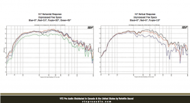
The Paraline device controls vertical beamwidth, the waveguide it is attached to controls horizontal beamwidth.
Below are horizontal and vertical response charts for the VTC EL210 HF drivers, a pair of Paralines on a single 90 degree waveguide.
The horizontal dispersion is very uniform, the vertical not so good.
Evidently they designed their Paraline with a 10 degree divergence, the ones I designed have no vertical divergence (in theory) while in practice something like about 5 degree at 16 K, widening with lower frequencies.
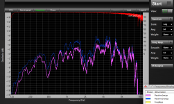
I'd post the charts of my Paraline polar response too, but unfortunately I deleted them at some point.
I did save a test which resulted in my removing 18mfd series "protection" caps, a holdover from the days of Phase Linear amps dumping the full DC supply voltage on the output when a transistor would fail.
Removing the capacitors made the crossover transition area much easier to "get right", and generally was an improvement in the EVDH1AMT's response.
I reused existing PA cabinet shells when building my Paralines, I was concerned that having parallel top and bottom horn walls might cause a standing wave problem.
To my surprise, angling the top or bottom walls on the prototype made no measurable difference in on axis response, in fact removing the top and bottom made no difference either!
When I saw (and heard) that attribute of the Paraline, I knew that it was doing something I had not experienced before.
The Paraline is very good for the desired application of multiple drivers on a single horn, or narrow vertical dispersion in a line array, but the ragged frequency response it imparts is a trade off that makes it a poor choice for home use.
Art
Attachments
Last edited:
I'm still not following and the data just looks like any other slot loaded diffraction horn.
What am I missing?
Do you understand how the radial horn is folded?
Basically it goes like this:
1) sound is radiated in the center of the circle. It expands 360 degrees.
2) Our wavefront is expanding in a ring, and hits that 'eye' shaped reflector.
3) When it hits the reflector, it's re-directed the other way.
4) It exits the Paraline and the ring shaped wavefront has been turned into a rectangular wavefront
The Paraline turns a ring into a rectangle.
If you modify the shape you can bend that rectangle; which is how you get a converging or diverging wavefront.
Earl,I'm still not following and the data just looks like any other slot loaded diffraction horn.
What am I missing?
The data does look like a slot loaded diffraction horn, which is what it is.
An old style slot loaded diffraction horn built like the Manta Ray would require about a 30 inch long pinched throat for 10 degree vertical dispersion, or 60 inch long pinched throat for 5 degree vertical dispersion.
The Paraline can do the same with a path length of a few inches, which is good both from a sonic standpoint as well as cabinet depth, and allows the mid driver's exit to be placed within 1/4 wavelength of the apparent acoustical center of the diffraction slot.
There are many different ways to accomplish the same end that don't require 30 to 60 inch throats, though the usual minimum seems around 5 inches, about 5 times the depth of a Paraline.
Having heard my Paraline small format system (10 HF drivers) along side a JBL 4889 line array (48 HF drivers) the Paralines seemed "cleaner", to me indicating the throat design is better.
That said, the Paraline does not sound as "clean" as a normal conical expansion horn.
Art
Art - OK now I understand. Its a way of taking the longish throat section of a standard diffraction slot horn and making it go radially/laterally by folding it instead of a single long axially oriented connecting section. Thus shortening the depth of the whole device. Downside, of course, is the bend will not be as clean a transmission as a straight through device - much more HF loss - but everything is a compromise.
4) It exits the Paraline and the ring shaped wavefront has been turned into a rectangular wavefront
The Paraline turns a ring into a rectangle.
This is exactly what I don't get.
I follow Arts discussion, but I don't follow this explaination.
Earl,
By changing the shape of the outside curvature of the expansion rate you can change the path length and this changes the wave shape at the exit of the paraline. There have been many shape transitions proposed and these are all attempts to change the exit waveform. I understand how the device is supposed to work but have always thought that the reversion from the abrupt directional changes has got to cause reversion of the waveforms in some manner that is little understood by those proposing this device. I understand the concept of foreshortening the waveguide but don't think the raged frequency response and loss of high frequency output is worth the effort for a hi fidelity speaker system. That is only my opinion and I am sure you can come to your own conclusions here.
By changing the shape of the outside curvature of the expansion rate you can change the path length and this changes the wave shape at the exit of the paraline. There have been many shape transitions proposed and these are all attempts to change the exit waveform. I understand how the device is supposed to work but have always thought that the reversion from the abrupt directional changes has got to cause reversion of the waveforms in some manner that is little understood by those proposing this device. I understand the concept of foreshortening the waveguide but don't think the raged frequency response and loss of high frequency output is worth the effort for a hi fidelity speaker system. That is only my opinion and I am sure you can come to your own conclusions here.
Definitely, one always needs to choose the compromises and tradeoffs, as no device is perfect in all respects.Art - OK now I understand. Its a way of taking the longish throat section of a standard diffraction slot horn and making it go radially/laterally by folding it instead of a single long axially oriented connecting section. Thus shortening the depth of the whole device. Downside, of course, is the bend will not be as clean a transmission as a straight through device - much more HF loss - but everything is a compromise.
Since line arrays don't use a "straight though" device, the difference in HF between an axially straight but vertically wavy or arced type of and a Paraline is not that huge, but the savings of 4 or 5 inches of depth between the coupler types allows a much longer, larger waveguide of a given horizontal beamwidth, and much lower pattern control for the Paraline, down to around 350-400 Hz on a 26.5" wide x 15" deep cabinet.
OK, but thats getting pretty far away from home audio. I always assume home audio here at DIY because thats what 90% of it is about. Pro audio is a different world with different requirements and tradeoffs. In home audio depth is not a big issue. Its never been a problem for me. Baffle area tends to be the bigger factor and paraline doesn't help that issue.
- Home
- Loudspeakers
- Multi-Way
- Square Pegs