Nice work, I appreciate the measurements.
Getting the midranges to play past 1500hz is maddening huh?")
a few things that might help:
1) If you use multiple compression drivers you can play 'em lower... Note that Danley used to use expensive coaxial compression drivers in some of the Synergy and Genesis horns, and he's mostly abandoned that. If I had to hazard a guess, I'd say that it's likely easier and more cost effective to use 2-4 compression drivers than it is to use a single coaxial compression driver. The main limitation keeping you from using a compression driver below 1000hz is excursion, so the use of multiple compression drivers on a Paraline is attractive because they sum very nicely at low frequencies.
Basically, investing $300 in a pair of compression drivers might be less hassle and less maddening than trying to get the midranges to go to 2000hz. Or you might consider some of the less expensive options from Celestion, thought that might open another can of worms. (I can't recall if the Celestion has as much displacement as the BMS. If it doesn't, then stick with the BMS, because displacement rules the day when it comes to setting the xover low.)
2) IMHO, if you're going to use a single frustum, you should have it centered in front of the cone of the midrange. This equalizes the pathlengths. A frustum is basically a crude phase plug, so centering it is important.
Getting the midranges to play past 1500hz is maddening huh?
a few things that might help:
1) If you use multiple compression drivers you can play 'em lower... Note that Danley used to use expensive coaxial compression drivers in some of the Synergy and Genesis horns, and he's mostly abandoned that. If I had to hazard a guess, I'd say that it's likely easier and more cost effective to use 2-4 compression drivers than it is to use a single coaxial compression driver. The main limitation keeping you from using a compression driver below 1000hz is excursion, so the use of multiple compression drivers on a Paraline is attractive because they sum very nicely at low frequencies.
Basically, investing $300 in a pair of compression drivers might be less hassle and less maddening than trying to get the midranges to go to 2000hz. Or you might consider some of the less expensive options from Celestion, thought that might open another can of worms. (I can't recall if the Celestion has as much displacement as the BMS. If it doesn't, then stick with the BMS, because displacement rules the day when it comes to setting the xover low.)
2) IMHO, if you're going to use a single frustum, you should have it centered in front of the cone of the midrange. This equalizes the pathlengths. A frustum is basically a crude phase plug, so centering it is important.
Last edited:
I need help here.
Nate you wrote that you used a lr4 crossover at 1000hz.
My understanding of the magic in unity/synergy is that you are using physical distances to compensate for phase angle change in the crossover.
The reason for the 1/4 wavelength distance from compression driver acoustic center to the midrange port is that the crossover have provided a phase change of 90 degree at the crossover point.
Is it not the lr2 that provides 90 degree phase change at crossover?
Or am I understanding it wrong?
My little understanding of crossover and phase comes mostly from Ranes "Linkwitz-Riley Crossovers: A Primer"
Linkwitz-Riley Crossovers: A Primer
Thanks for the thoughts guys.
When I did the ports as they are, I wasn't worried about getting it centered because I figured that the path lengths from the cone itself in the chamber to the port would be short enough that any effect would be outside the bandpass. Thinking about it I'm probably right on the edge.
Another thing I didn't consider (as you guys mentioned) along those lines is the furthest part of the cone from the center of the comp driver entrance is nearly 2.5" farther away than the near side of the cone. Interesting to think about, and that could also be limiting my bandwidth, even though it seems on the surface counter-intuitive to move the ports farther out. I'll try moving the ports this weekend.
Nissep - that's more than I want to wrap my brain around at this hour but you're probably right. I only went 4th order because that's what fell out from the way the mid ports are configured and that's where the comp driver falls off. I added 1st order electrical high and low-pass to the drivers to hit about 4th order acoustic and to protect the drivers. Mainly, I just wanted a quick impression of how these things are going to sound!
When I did the ports as they are, I wasn't worried about getting it centered because I figured that the path lengths from the cone itself in the chamber to the port would be short enough that any effect would be outside the bandpass. Thinking about it I'm probably right on the edge.
Another thing I didn't consider (as you guys mentioned) along those lines is the furthest part of the cone from the center of the comp driver entrance is nearly 2.5" farther away than the near side of the cone. Interesting to think about, and that could also be limiting my bandwidth, even though it seems on the surface counter-intuitive to move the ports farther out. I'll try moving the ports this weekend.
Nissep - that's more than I want to wrap my brain around at this hour
but you're probably right. I only went 4th order because that's what fell out from the way the mid ports are configured and that's where the comp driver falls off. I added 1st order electrical high and low-pass to the drivers to hit about 4th order acoustic and to protect the drivers. Mainly, I just wanted a quick impression of how these things are going to sound!I'll try moving the ports this weekend.
Actually I won't, at least not with 4 drivers. The ports are already close to the Paraline fold as it is. I did cut some extra driver plates in anticipation of trial and (lots of!) error, so I might try out 2 drivers with centralized ports and frustrums.
That's one of the nice things about these Paralines. I can fairly easily redo the driver configuration on a flat plate without having to cut up the horn shell.
I'm also going to look into reticulated foam or poly fill in the frustrums as well as the Paraline itself to smooth the response.
There has been some talk about using the Paraline as a bass-/midbasshorn. If you design a tall Paraline, you should be able to reach down to bass/midbass territory. I have spent some time visualizing this and thinking about how nice it would be to shorten the depth of a proper 60-300 horn with a combination of a tall Paraline and a relatively short horn in front.
I have tried to model the Paraline in Hornresp. With only one driver and designing for midbass duties, I have tried different sizes for S1, S2 and L12. There is not much horn-gain in the lower frequencies with a Paraline designed with 1 inch height in the "layers", even modelling a 200cm version.
Of course, I may be doing this all wrong. How would one go about modelling a Paraline in Hornresp? Naively, I used S1 for entry, S2 for exit/the "slot" and L12 for pathlength=A1 in the patent. Have I missed something?
I tried searching for Paraline and Hornresp but could not find any info.
Using 2" thickness/heigth in the layers of the Paraline improved matters quite a lot in my (most probably wrong) Hornresp model.
A 120cm tall Paraline combined with a conical horn of 60cm with (120cm height) and 52cm length gives me F3 70Hz and 106dB sensivity. As the total pathlength is around 112 cm there should be some gain even at frequencies under 100Hz? I set the backchamber at 15 liters, have not played around much with the other parameters.
I used a JBL 2226 for modelling, even if this driver is not optimal for horns. Having seen quite experienced people using it in La Scala and Altec horns, I am hoping to find use for my stock of this driver.
But am I modelling this as it should be done?
Naturlyd,
I suspect that what you are seeing is the fact that the Paraline and conic horn combination is more of a directional device than a gain device. You only have to go and look at some of the original horn development to see that a conic section is not an efficient shape as far as gain is concerned. It has been chosen in the original design concept to control directivity in large arrays. What you have given up in efficiency is made up by more amplifier power and lots of eq.
When you are looking at the output of the Paraline you need to look at the complete Paraline and horn combination, not just to the initial section only. S2 should be the final horn mouth size not the end of the Paraline.
Naturlyd,
I suspect that what you are seeing is the fact that the Paraline and conic horn combination is more of a directional device than a gain device. You only have to go and look at some of the original horn development to see that a conic section is not an efficient shape as far as gain is concerned. It has been chosen in the original design concept to control directivity in large arrays. What you have given up in efficiency is made up by more amplifier power and lots of eq.
When you are looking at the output of the Paraline you need to look at the complete Paraline and horn combination, not just to the initial section only. S2 should be the final horn mouth size not the end of the Paraline.
Thank you very much, Kindhornman, I did not realise that Conicals is so much less efficient regarding gain, but do remember that TD wrote about the upside of controlled directivity. For midbass I think gain is my main priority.
I did model the horn in two sections, first the Paraline S1-S2 and then a conical section S2-S3. The Paraline do have a rather narrow expansion with S1 set to 340cm2 (2:1 in compression with JBL 2226) and S2 set to 528cm2 (a 120cm tall and 4.4cm wide slot/exit). Using a conical section after the Paraline, the results from using a wider expansion looks much better to this untrained eye, with more lowfrequency gain and smoother graphs.
Things I need to learn:
- will a "slimmer" Paraline with D1 less than A1 and a diverging wavefront "load" the following horn better as it "uses" the vertical part of the following horn to a greater extent?
- As the Paraline output is rather extreme, having a more or less flat wavefront in the vertical and 360 in the horisontal, how will this affect the next section of the horn when optimizing for midbass/bass purposes?
- Do I have to use a conical section after the Paraline to get the optimal interface? Why not a exponential horn?
- Do the shading-effect on the Paraline affect the interface with a following horn-section?
I tried searching for Paraline and Hornresp but could not find any info.
Using 2" thickness/heigth in the layers of the Paraline improved matters quite a lot in my (most probably wrong) Hornresp model.
A 120cm tall Paraline combined with a conical horn of 60cm with (120cm height) and 52cm length gives me F3 70Hz and 106dB sensivity. As the total pathlength is around 112 cm there should be some gain even at frequencies under 100Hz? I set the backchamber at 15 liters, have not played around much with the other parameters.
I used a JBL 2226 for modelling, even if this driver is not optimal for horns. Having seen quite experienced people using it in La Scala and Altec horns, I am hoping to find use for my stock of this driver.
But am I modelling this as it should be done?
I need a break from writing code at work, so thought I'd throw together some quick instructions on basshorn paralines.
here is how I would do it.
1) First off, we need to set a goal for the project. I'm going to 'aim' for an F3 of about 30hz. My selection of 30hz is a compromise between home theater and music. (IMHO home theater needs to go to about 20hz, music needs a sub that does 35hz or so.)
Here is the math on what size Paraline we need.
The Paraline cutoff will be equivalent to the distance from the center of the Paraline to the 'top' of the Paraline, divided by four. For instance, with a 366cm x 732cm board, the distance from center to top is 366cm. The formula is (speed of sound / distance / 4), or (34000 cm per second / 366cm / 4), or 23hz.
An externally hosted image should be here but it was not working when we last tested it.
2) Now that we know how low our Paraline will play, we have to pick a driver for the project. I'm going with a back loaded horn using the ubiquitous MCM 55-2421. I'm selecting this driver for two reasons. First, it's twenty five bucks. Second, it's a very "horn-friendly" driver, due to it's low qes.
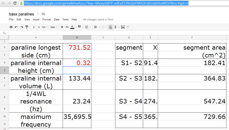
In order to ease the use of hornresp with Paralines, I made a spreadsheet. The pic above shows the spreadsheet.
An externally hosted image should be here but it was not working when we last tested it.
Using the spreadsheet is really simple, you simply plug in the longest dimensions of your paraline, and the internal thickness.
Once you plug in those two numbers, the spreadsheet will give you the following data:
1) it'll tell you the quarter wavelength frequency of your horn. For a BLH I'd aim for 0.707 multiplied by the FS of the driver. For instance, a driver with an FS of 30.95hz would have an FB of 22hz.
2) it'll tell you the area of the segments in hornresp. For instance, it'll tell you what to plug in for entries "S2,S3,S4 and S5" in hornresp
3) it'll tell you the maximum usable frequency of the Paraline
4) it'll tell you the internal volume of a Paraline
you can get the spreadsheet here:
https://docs.google.com/spreadsheet/ccc?key=0AoryriIdTP-edExZT29nQnFMVGFrd1Vxb05oWEVYRmc#gid=0
You may need to cut and paste the formula into excel, or your own google spreadsheet. I set up the spreadsheet so that you can see it, but you can't change it. I did this so that no one messes with the formulas.
So now that we have a few pieces, we can model our sub in Hornresp. We have assembled the following:
1) we've chosen a target cutoff for the sub
2) we've chosen a sub that will work with that cut off (mcm 55-2421)
3) I've provided a spreadsheet that'll calculate the area of the segments and the cutoff of the horn
4) we have s/w that will model the horn (hornresp)
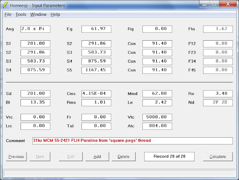
Using my spreadsheet, I came up with the following sim:
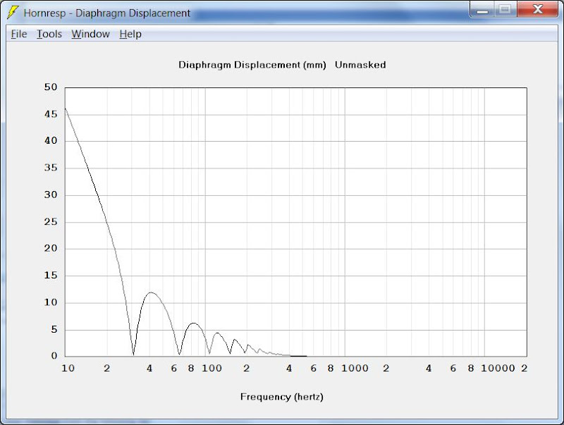
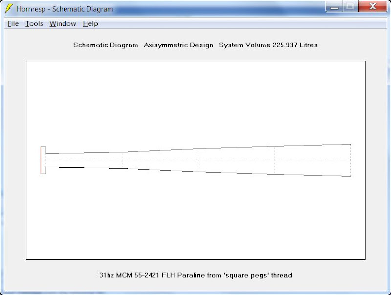
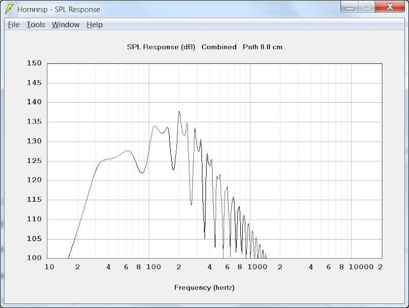
Here's some observations about my sim:
1) note how thin the sub is. It's ONE FIFTH of an inch thick.
2) I had to use four subs. Not for power handling, but simply to flatten out response on the low end. Another option would be to use two subs and a thickness of one tenth of an inch, but I don't know anyone that sells wood that thin!
3) The Paraline dimensions are ridiculously large. 24 feet on one side by twelve on the other.
4) Output and efficiency are quite good. Nearly 130dB at 60hz and 125dB at 40hz.
1) we've chosen a target cutoff for the sub
2) we've chosen a sub that will work with that cut off (mcm 55-2421)
3) I've provided a spreadsheet that'll calculate the area of the segments and the cutoff of the horn
4) we have s/w that will model the horn (hornresp)
Using my spreadsheet, I came up with the following sim:
Here's some observations about my sim:
1) note how thin the sub is. It's ONE FIFTH of an inch thick.
2) I had to use four subs. Not for power handling, but simply to flatten out response on the low end. Another option would be to use two subs and a thickness of one tenth of an inch, but I don't know anyone that sells wood that thin!
3) The Paraline dimensions are ridiculously large. 24 feet on one side by twelve on the other.
4) Output and efficiency are quite good. Nearly 130dB at 60hz and 125dB at 40hz.
So... can you do a tapped horn as a Paraline? (possibly an ignorant question, I'm still foggy about paralines).
You can do a front loaded horn, a back loaded horn and tapped horns in a Paraline.
The output of the tapped horn will be virtually identical to the FLH because the front and the back of the driver are so close to the throat and the mouth, respectively.
Also note that in the real world I'd expect that the 'ripple' would be a lot less severe than hornresp predicts, since the Paraline acts as a baffle seperating the front and the back wave in a manner that's much more substantial and effective than in a typical folded horn.
In a lot of ways I think that Paraline back loaded horns are an interesting alternative to conventional dipoles.
If I didn't make it clear, here's how my spreadsheet 'maps' to hornresp:
1) the area of the fields S2, S3, S4, and S5 are lifted directly from my spreadsheet and pasted into HORNRESP
2) The area of the horn throat is the area of the cone. This one is a bit tricky, because theoretically the area at the center of the Paraline is zero(!) Of course that isn't the case in the real world because there's a volume of air between the cone and the woofer and the Paraline. That volume is fairly substantial; as much as 200-300 sq cm for an 8" woofer. This volume can be reduced if necessary, by putting a baffle in front of the cone.
3) Be sure that the Paraline internal volume from my spreadsheet is in the same ballpark as the volume of the horn from hornresp. If not, you made a mistake somewhere
4) Note that the internal height of the Paraline from my spreadsheet has a direct effect on the overall volume of the horn, and the area of segments S2, S3, S4, and S5
5) The length of the conical segments is constant. It is equivalent to the first value of "X" from cell E4 of the spreadsheet.
Thanks a lot for answering many of my questions, PB. While I have learned a lot from your earlier posts about Unity and Paraline, now I am actually left with even more questions.
This may have been addressed earlier, but why do you split the Paraline into 4 segments in your spreadsheet/Hornresp? This is the eye-shaped Paraline?
- Referring to the patent its difficult to see why you split the Paraline into 4 segments, each with a quarter of the total pathlength. Wouldnt the pathlength of section D1 and D2 be close to the total pathlength? If S1-S2 was the entry and rather short, S2-S3 was D1, S3-S4 was the 180 deg. bend and also short, and S4-S5 was D2, I could understand the consept. Could someone please explain?
- If the Paraline horn is a round horn with 360 degree horisontal spread (like the filling in an Oreo cookie) thats folded, why do we need to split the path into sections? Do the folds in the Paraline truncate or in other ways affect the pathway in such a way that we need to section the horn to simulate the effect? If not, then why do we need more than S1 as the entrance and S2 as the exit/slot to simulate a Paraline horn? Is not the pathway expanding in a linear fashion between those two points?
This is fun!! Just to make my design target clear, the overall goal is to have a FLH bass/midbass 80-400Hz with proper hornloading but I could settle with somewhat less BW. My interest in the Paraline, besides a fascination for brilliant consepts, is the promise of reducing the depth of the horn, and a hope that the folds in the Paraline would not affect the upper bass/lower midrange to much. But if a Paraline mainly is a directivity-device and do not contribute much to the loading in the lower frequencies, I guess I am better of with a "scorpion-style" midbasshorn with only one, gentle bend. My limited experience with folded FLH >250Hz has not been promising.
Like many other, its not the overall bulk of a hornsystem thats the problem, its the depth of proper horns. The system will use distributed subs <80Hz and large horn >400Hz.
And the testing continues.......
I had an extra driver plate, so I set it up for 2 mid drivers with the frustrum and port at the center of the mid cone, rather than offset as I have it on my 4 mid Paraline. The central port puts it about 3.5" away from the CD entrance. The first port iteration was a .25" wide x .5" long slot port (red curve), then I went with a .5" dia port (green curve). The lavender curve is my 4 driver Paraline with the offset ports about 2.2" from the CD entrance. These were all taken on the 60x40 conicals I built.
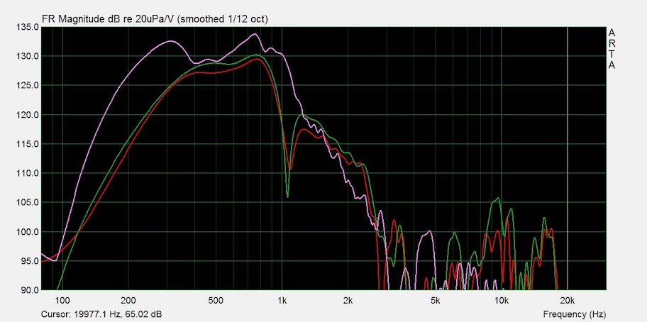
The 1khz notch on the centered port versions corresponds pretty well with the 3.5" distance from the CD entrance. You can see a bit extra output past that notch though over the offset port config.
Next, I measured right out of the mid port, not on the Paraline to take that out of the equation. The purple curve is the central port, yellow is the offset port, and red is the mid response on the Paraline attached to the horn:

A good bit more hf extension with the centralized port vs the offset port, although the previous test shows the importance of having the mid entry as close as possible to the CD entry. Can't I have my cake and eat it too?
I'm thinking the BMS 4540nd is the answer here. Smaller in diameter than my 4524s, and I can make a screw on adapter that will sit the screen on the driver exit right down into the Paraline itself. This way I can eliminate about 1.25" just with the driver itself, plus I can move the drivers in a bit more and get the mid ports in a more central location without sacrificing the distance to the CD entrance. Total balancing act here!
The deep notches in the CD response have been bothering me as well. I thought I remembered a pretty workable response of the CD on the Paraline and horn with no mid ports but I can't find the graphs. I figured the notches were caused by the mid ports, so I blocked them off and measured the CD on the Paraline on the horn again (green is no mid ports, red is with the mid ports):

The ports seem to add to the 5.2khz notch, but not as much as I thought and the others are not affected. I've got my Paralines lined with open cell foam sold for shop vacs. The mid ports and frustrums have the foam as well. Lost the graphs from that bit of testing too, but the foam helps smooth things out a good bit past 8-9khz.
I had an extra driver plate, so I set it up for 2 mid drivers with the frustrum and port at the center of the mid cone, rather than offset as I have it on my 4 mid Paraline. The central port puts it about 3.5" away from the CD entrance. The first port iteration was a .25" wide x .5" long slot port (red curve), then I went with a .5" dia port (green curve). The lavender curve is my 4 driver Paraline with the offset ports about 2.2" from the CD entrance. These were all taken on the 60x40 conicals I built.
The 1khz notch on the centered port versions corresponds pretty well with the 3.5" distance from the CD entrance. You can see a bit extra output past that notch though over the offset port config.
Next, I measured right out of the mid port, not on the Paraline to take that out of the equation. The purple curve is the central port, yellow is the offset port, and red is the mid response on the Paraline attached to the horn:
A good bit more hf extension with the centralized port vs the offset port, although the previous test shows the importance of having the mid entry as close as possible to the CD entry. Can't I have my cake and eat it too?
I'm thinking the BMS 4540nd is the answer here. Smaller in diameter than my 4524s, and I can make a screw on adapter that will sit the screen on the driver exit right down into the Paraline itself. This way I can eliminate about 1.25" just with the driver itself, plus I can move the drivers in a bit more and get the mid ports in a more central location without sacrificing the distance to the CD entrance. Total balancing act here!
The deep notches in the CD response have been bothering me as well. I thought I remembered a pretty workable response of the CD on the Paraline and horn with no mid ports but I can't find the graphs. I figured the notches were caused by the mid ports, so I blocked them off and measured the CD on the Paraline on the horn again (green is no mid ports, red is with the mid ports):
The ports seem to add to the 5.2khz notch, but not as much as I thought and the others are not affected. I've got my Paralines lined with open cell foam sold for shop vacs. The mid ports and frustrums have the foam as well. Lost the graphs from that bit of testing too, but the foam helps smooth things out a good bit past 8-9khz.
Ok, I found this thread following another thread... I had seen the Paraline on the pro website that showed the construction animation some time back. Scratched my head.
Thought it might be cool for PA applications, but maybe not home use...
I agree with Kindhornman's earlier comment that this is a diffraction slot loading... sure looks and seems to act like one.
But all this talk about it has me thinking. Has anyone mapped out the expansions unfolded?? Reading through my swiss cheese synaptic conceptotron auxilliary unit came up with a thought. This looks a bit like the expansion found on the end of a Mantaray horn. That one lets the wavefront expand conically in the "vertical" dimension (assuming you put the horn that way), while actually reducing the dimension, or keeping it almost parallel (maybe it just expands slightly - haven't looked at one for years now), this results in a tall thin slot, which is then loaded into the end of a conical horn (it actually has one or two conical "steps" - but that's not important).
Seems to me that if you made the unfolded paraline you'd have an impossible to make work almost 180 degree vertical expansion and nil horizontal expansion, terminating with that diffraction slot and phase plug thingie...
Ok so you can't build that in practical terms, but if you took two drivers, left and right, aimed them at a center point, and then had an expansion with a slot open in the center, that'd be more or less this paraline unfolded.
A try at ascii art:
C|< | >D
A little imagination required. Left and right compression drivers C| and D, the conic expansion with nil expansion in the direction perpendicular to this page are < and > and the exit on one side only is | . Hope this makes some sense.
Actually this double driver version can be built... the thing that can't be gotten without the folding is the equal distance to a vertical slot from a single point! That's the beauty of Danley's idea it seems to me.
This assumes that the air in the chamber acts in a fashion that actually requires or creates equal path lengths and that it doesn't act as a single hydraulic volume. There's some question there... but I can accept the idea of equal path lengths.
Anyone see it this way besides me?
_-_-
... Has anyone mapped out the expansions unfolded?? ... Seems to me that if you made the unfolded paraline you'd have an impossible to make work almost 180 degree vertical expansion and nil horizontal expansion, terminating with that diffraction slot and phase plug thingie... ...
An unfolded paraline is 2 circular disks mounted a short distance apart, with a driver attached to a hole at the centre of one of the disks. 360 degree expansion in one plane and none in the other plane.
sure, two discs, hole in the center of one, 1/4" apart, exit on the edges... except that does not converge to a straight line. Even cut in half.
And actually, only the first part of the expansion is 360 degrees... the second fold is not, otherwise it would not converge on a straight line...?
And actually, only the first part of the expansion is 360 degrees... the second fold is not, otherwise it would not converge on a straight line...?
And the testing continues.......
I had an extra driver plate, so I set it up for 2 mid drivers with the frustrum and port at the center of the mid cone, rather than offset as I have it on my 4 mid Paraline. The central port puts it about 3.5" away from the CD entrance. The first port iteration was a .25" wide x .5" long slot port (red curve), then I went with a .5" dia port (green curve). The lavender curve is my 4 driver Paraline with the offset ports about 2.2" from the CD entrance. These were all taken on the 60x40 conicals I built.
The 1khz notch on the centered port versions corresponds pretty well with the 3.5" distance from the CD entrance. You can see a bit extra output past that notch though over the offset port config.
Next, I measured right out of the mid port, not on the Paraline to take that out of the equation. The purple curve is the central port, yellow is the offset port, and red is the mid response on the Paraline attached to the horn:
A good bit more hf extension with the centralized port vs the offset port, although the previous test shows the importance of having the mid entry as close as possible to the CD entry. Can't I have my cake and eat it too?
I'm thinking the BMS 4540nd is the answer here. Smaller in diameter than my 4524s, and I can make a screw on adapter that will sit the screen on the driver exit right down into the Paraline itself. This way I can eliminate about 1.25" just with the driver itself, plus I can move the drivers in a bit more and get the mid ports in a more central location without sacrificing the distance to the CD entrance. Total balancing act here!
The deep notches in the CD response have been bothering me as well. I thought I remembered a pretty workable response of the CD on the Paraline and horn with no mid ports but I can't find the graphs. I figured the notches were caused by the mid ports, so I blocked them off and measured the CD on the Paraline on the horn again (green is no mid ports, red is with the mid ports):
The ports seem to add to the 5.2khz notch, but not as much as I thought and the others are not affected. I've got my Paralines lined with open cell foam sold for shop vacs. The mid ports and frustrums have the foam as well. Lost the graphs from that bit of testing too, but the foam helps smooth things out a good bit past 8-9khz.
If you mess around with hornresp, you'll notice that you get peaks and dips in frequency response when a horn is too small. If that's the thing that's causing the peaks and dips in your response, there's a couple of ways to fix it:
1) use a horn with larger volume (IE, use a Paraline with an internal height that's larger)
2) use a compression driver with higher BL; IIRC motor force is able to smooth out the peaks and dips in a horn that's too small
If the BMS 4524 is a ferrite compression driver, than the neo 4540 may help here. I wish I had a proper testing rig set up here; I have both the neo 4540 and the neo Celestion CDX1-1425 here.
- Home
- Loudspeakers
- Multi-Way
- Square Pegs