It seems to me that if a considered design were to be finalised using a specific driver that gave good results, a Kit of parts could be made available, made from a CNC machined laminated material that made up the five layers of the design.
This could run as a "Group Buy" and would therefore be very useful in evaluating the efficacy of the Patented design by a wider group of people.
Just a thought!
I emailed Danley a couple weeks back, and asked him if he'd license it to me. If he gave the green light, I'd make a Paraline in Blender, export it to DXF, then have it cut professionally on a CNC router.
Haven't heard back (yet)
If I'm not mistaken, Paul Spencer did something similar with his Synergy Horn flatpacks, and this is also how the Lambda Unity Horns came to be.
If I got the green light, these would be designed for the car.
I think this is a particularly attractive project for Kickstarter, because the cost is fairly low, but the precision has to be very high. For instance, if the center of the Paraline is off by 1/4", the high frequency response will change. Basically a Paraline is easier to fabricate than a conventional horn, but the accuracy requirements are quite a bit stricter.
Patrick,
When you are cutting your crude models you are just cutting using a saw or such. Have you looked at what differences there would be if the inside boards and outside cuts were radius cuts instead of the straight cuts. I would think that would improve the high frequency response instead of the sharp edges and square outside corners?
Steven
Patrick,
When you are cutting your crude models you are just cutting using a saw or such. Have you looked at what differences there would be if the inside boards and outside cuts were radius cuts instead of the straight cuts. I would think that would improve the high frequency response instead of the sharp edges and square outside corners?
Steven
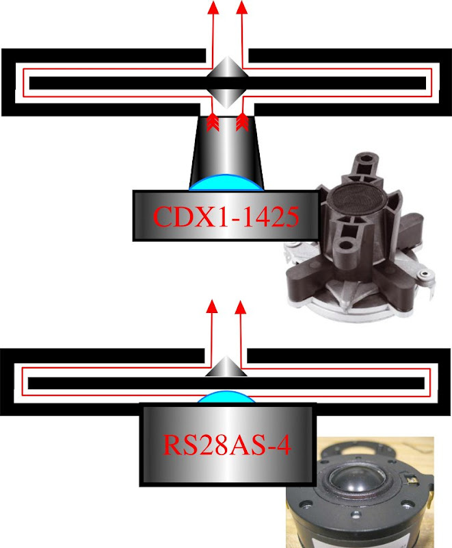
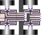
my new designs have reflectors at the 90 degree turns, like in the pic above
An externally hosted image should be here but it was not working when we last tested it.
This design from a few days earlier is lacking reflectors. (Note the 90 degree bends are square)
At these small dimensions, I doubt it would make a substantial difference below about 5-10khz, but it should help from 10-20khz. If you play around with the reflectors in Hornresp using the ripple pool simulator, you'll notice that high frequency extension is extended via the use of reflectors.
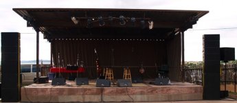
The Paraline line array I built using Eminence Alpha 8 and EV DH1AMT was the first PA system I have mixed on where the PA output sounds more "high fidelity" than the Sony MDR 7506 headphones, or the GK Ultraphones which also use the MDR 7506 transducer I use for reference.jerryo,
I have not heard these either. What I know is that this is borrowed from a pro-audio application for sound reinforcement with a coherent wavefront/ I don't really think that in its present form I would call it a high fidelity device. but I have not heard it so I could be wrong.........
I had used the same transducers in an MTM arrangement in the same cabinet shell, the difference between the Paraline/offset horn and the MTM was a huge improvement in terms of off axis uniformity and resistance to degradation caused by wind.
In terms of "ruler flat" frequency response, the Paraline will not appear as "high fidelity" as some transducers, but for the things I consider most important for hi-fi at a distance, haven't found anything better in a modular system.
Art Welter
Hi weltersys,
what is the frequency range that your paralines operate over, and do you have any photo's?
Whilst we are the subject, what would be the widest frequency response that one could expect to achieve using a paraline of reasonable dimensions?
What would be the best material to use for the construction?
what is the frequency range that your paralines operate over, and do you have any photo's?
Whilst we are the subject, what would be the widest frequency response that one could expect to achieve using a paraline of reasonable dimensions?
What would be the best material to use for the construction?
Patrick (John),
In a paraline config the dome tweeter does not generate a plane wave. Also the surround would occupy sufficient space (height) in the gap?
While the former would probably result in a drop in the highs which can be cured by eq, I have doubts whether the latter can be cured.
How bad would these issues be?
Goldy
I used birch plywood. The Paraline guts are posted in #92.Hi weltersys,
what is the frequency range that your paralines operate over, and do you have any photo's?
Whilst we are the subject, what would be the widest frequency response that one could expect to achieve using a paraline of reasonable dimensions?
What would be the best material to use for the construction?
Cabinet dimensions are 26.5 wide by 11.25 tall and 15" deep.
Using a pair of Keystone 18" subs, 28 eights, 10 EVDH1AMT, crossover points are 100 Hz, 680 & 1100 Hz, an underlap in the high crossover results in an acoustical crossover around 800 Hz.
Art
Attachments
Patrick (John),
In a paraline config the dome tweeter does not generate a plane wave. Also the surround would occupy sufficient space (height) in the gap?
While the former would probably result in a drop in the highs which can be cured by eq, I have doubts whether the latter can be cured.
How bad would these issues be?
Goldy
Could you elaborate on your concerns about the surround? Trying to figure out why that would be an issue. (probably not visualizing it right)
Maybe someone can clarify things for me a little here? Just what does this paraline-like thing... **do**??
I've read Tom's patent, and interpreted it as providing a way to take one or more plane wave sources and transform them into a line source. But in PB's post (#203), it appears a planewave source or a dome drives a small opening, the pressure expands out... then compresses again to an area about the same size as it entered, then exits?? Is the goal delay? Or changing the wavefront shape (i.e., a phase plug)? I'm clearly missing something. I can see the value in making a horn shorter (if that's the goal), but can't see how any of this does that. Obtaining a delay can be useful (I could use a shallow way to delay the output of a 1" driver by a few inches), but does the expansion/recompression do that?
Or is the interest about a way to combine midrange and tweeter signals into a single aperture? (If so, shouldn't the result be at a larger area than the tweeter originally fed)? Does dropping everything to two dimensions instead of three (if that's what the 'trick' is) make something new possible? Not sarcastic here, just having difficulty seeing what could be made, other than Tom's line source.
What is the goal here?
Maybe someone can clarify things for me a little here? Just what does this paraline-like thing... **do**??
I've read Tom's patent, and interpreted it as providing a way to take one or more plane wave sources and transform them into a line source. But in PB's post (#203), it appears a planewave source or a dome drives a small opening, the pressure expands out... then compresses again to an area about the same size as it entered, then exits??
Hey Bill,
I've really enjoyed your Synergy horn project. I'll likely build another Paraline today using the same drivers.
An externally hosted image should be here but it was not working when we last tested it.
Here's a 3D view of the device, stolen from Yorkville
Actually, this is the first time that it occurred to me that the exit of the Paraline is an exact multiple of the entrance, and that the area of the exit is the same as the height of the Paraline multiplied by the area of the input.
I'll have to crunch the numbers to be sure that is the case, but it appears that's the deal.
Is the goal delay? Or changing the wavefront shape (i.e., a phase plug)? I'm clearly missing something. I can see the value in making a horn shorter (if that's the goal), but can't see how any of this does that. Obtaining a delay can be useful (I could use a shallow way to delay the output of a 1" driver by a few inches), but does the expansion/recompression do that?
Or is the interest about a way to combine midrange and tweeter signals into a single aperture? (If so, shouldn't the result be at a larger area than the tweeter originally fed)? Does dropping everything to two dimensions instead of three (if that's what the 'trick' is) make something new possible? Not sarcastic here, just having difficulty seeing what could be made, other than Tom's line source.
What is the goal here?
There are a lot of goals, but I'd say the main one is the ability to put a horn of nearly any length into a depth of 1.25". As noted above, it appears that the mouth is an exact multiple of the throat. So you can get a mouth of any size you'd like, as long as you have enough space to expand OUT. IE, the Paraline is quite pointless if you don't have a lot of height or width. But in a home, height and width isn't really the problem.

Depth is the problem, as demonstrated by the pic above
")
Keep in mind, there's nothing magical about the Paraline. It's simply a novel way to fold a horn.
Last edited:
Maybe someone can clarify things for me a little here? Just what does this paraline-like thing... **do**??
I've read Tom's patent, and interpreted it as providing a way to take one or more plane wave sources and transform them into a line source. But in PB's post (#203), it appears a planewave source or a dome drives a small opening, the pressure expands out... then compresses again to an area about the same size as it entered, then exits??
What is the goal here?
I'm with you, as of this point, I think it's a very innovative way to convert a point source to a line source.
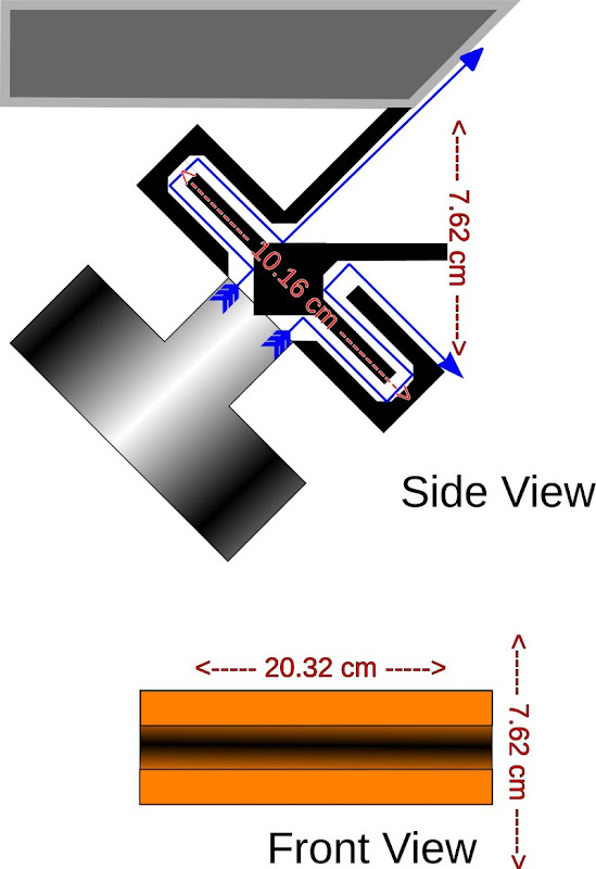
It took way longer than I'd like to admit, but I made an 'evolution' of the Paraline. This 'evolution' allows the device to be mounted ninety degrees off-axis.
In particular, it's good for cars. You can have it fire UP into the dash, then bend the wave ninety degrees the other way, so it ends up firing forward.
If you look at the Danley Paraline, it might seem like one could simply fire the Paraline straight up, but this won't work. The wavefront from one side of the Paraline would lag the other side of the Paraline by about 2-4 centimeters. That may not sound like a big difference, but it would basically nuke all output above 10khz.
My 'evolution' of the Paraline adjusts the pathlengths, so that the output at the mouth is still in phase, even though the Paraline is on it's side.
Besides being useful in cars, there are some other uses:
#1 - you could velcro this right onto something flat. For instance, place it UNDER a flat screen tv. The flat surface will extend the horn mouth.
#2 - In a car, you could not only put these under the dash, you could put them right ON the glass. The surface is perfectly flat, so the entire windshield of the car could extend the horn curve. Personally, I'm really curious how this would sound because the idea of having a horn that's the size of an entire car windshield sounds pretty exciting Also, glass is an excellent material for a horn, because it's stiff and it's strong.
details here:
DIYMA Car Audio Forum - View Single Post - Biggs^H^H Poppa
construction pics coming soon.
In particular, it's good for cars. You can have it fire UP into the dash, then bend the wave ninety degrees the other way, so it ends up firing forward.
If you look at the Danley Paraline, it might seem like one could simply fire the Paraline straight up, but this won't work. The wavefront from one side of the Paraline would lag the other side of the Paraline by about 2-4 centimeters. That may not sound like a big difference, but it would basically nuke all output above 10khz.
My 'evolution' of the Paraline adjusts the pathlengths, so that the output at the mouth is still in phase, even though the Paraline is on it's side.
Besides being useful in cars, there are some other uses:
#1 - you could velcro this right onto something flat. For instance, place it UNDER a flat screen tv. The flat surface will extend the horn mouth.
#2 - In a car, you could not only put these under the dash, you could put them right ON the glass. The surface is perfectly flat, so the entire windshield of the car could extend the horn curve. Personally, I'm really curious how this would sound because the idea of having a horn that's the size of an entire car windshield sounds pretty exciting
Also, glass is an excellent material for a horn, because it's stiff and it's strong.details here:
DIYMA Car Audio Forum - View Single Post - Biggs^H^H Poppa
construction pics coming soon.
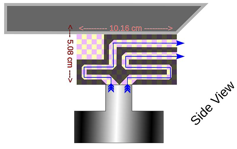
forgot to mention - the weird purple and yellow checkerboard is just there to measure the pathlength. The reason that the thing took so long is that I had to adjust the entrance, exit, and horn mouth centimeter by centimeter until everything lined up. The pathlengths are identical from compression driver exit all the way to the mouth.
This looks great you already got two novel foldings for this stuff!
Sorry for insisting, but I can't wrap my head around what's the relation between the length of the paraline path and the cutoff frequency. I mean, suppose if I have a midrange in a paraline capable of output down to 400hz, how do I calculate the paraline to achieve this output?
I've looked in Danley's patent, but that's focused on getting a line-source.
Thanks!
This looks great you already got two novel foldings for this stuff!
Sorry for insisting, but I can't wrap my head around what's the relation between the length of the paraline path and the cutoff frequency. I mean, suppose if I have a midrange in a paraline capable of output down to 400hz, how do I calculate the paraline to achieve this output?
I've looked in Danley's patent, but that's focused on getting a line-source.
Thanks!
Danley elaborates on this question in the eighth post on this thread:
Mid cone driver slots and holes
A lightbulb went off over my head when I read his comments, as I'd messed around with bending waves for years. Over the years I'd invested gobs of time building some gorgeous oblate spheroidal waveguides that I'd bent around a ninety degree curve. But they didn't work at all. (That's the reason I haven't posted them - my attempts at bending sound didn't work.)
The reason that my 'bent' waveguides didn't work is very simple. The pathlengths weren't equal.

For instance, a lot of people have made transmission lines using PVC. And these gorgeous, gentle gradual bends look great. But they don't work. The reason they don't work is that the pathlength on the outside of the curve is longer than the pathlength on the inside of the curve.
An externally hosted image should be here but it was not working when we last tested it.
That's why the Paraline needs these ultra-abrupt bends. If you look at the device, it looks like it would work horribly. In audio we're simply not accustomed to devices which bend waves so violently. But these ultra-short bends actually work better, because they keep the pathlengths equal. Well, technically, the inside and the outside of the bend is different in length, but the difference is much much less than you'd get with a conventional bend. Basically if you want to bend sound you want the inside and outside of the curve to be as close as humanly possible. The shortest distance between two points is a straight line, which is why we use reflectors in the Paraline bends, not curves.
Bruce Edgar figured this out thirty years ago, and there's a Speaker Builder article on Volvotreter's page which covers the same subject. (Thanks to Jason Winslow for the tip)
To give you an idea of just how tight our tolerances are, our margin of error is just 0.85cm at 10khz. Once the pathlength differences start to exceed 0.85cm, we start to get comb filtering. At 20khz, the margin of error is 0.425cm.
So PVC pipe is wildly inappropriate, but a flat disc works very nicely. And a Paraline is simply a disc-shaped horn that's been folded. A bit like a Smith horn, but a full 360 degrees instead of 135, and much shorter in height.
Last edited:
This looks great you already got two novel foldings for this stuff!
Sorry for insisting, but I can't wrap my head around what's the relation between the length of the paraline path and the cutoff frequency. I mean, suppose if I have a midrange in a paraline capable of output down to 400hz, how do I calculate the paraline to achieve this output?
I've looked in Danley's patent, but that's focused on getting a line-source.
Thanks!
The cutoff frequency is determined the same as it is for all horns. Its area change across a defined distance. The effective flare rate is from the tap in point over the length it takes to double in area. This is covered in the Synergy patent. Let's say the mids tap into a point on the paraline that has an area of 30cm^2. Next find the length it takes for it to expand out to 60cm^2. Fire up Horn Response and plug in 30 for S1, 60 for S2 and whatever your length was to get out to 60cm^2. Have Horn Response calculate what the effective exponential flare rate is and you’re done.
Patrick,forgot to mention - the weird purple and yellow checkerboard is just there to measure the pathlength. The reason that the thing took so long is that I had to adjust the entrance, exit, and horn mouth centimeter by centimeter until everything lined up. The pathlengths are identical from compression driver exit all the way to the mouth.
Using a mirror left and right (up and down in your picture) set of drivers, adding a rear set of drivers, and delaying the front drivers to the rear, one could achieve a density of sixty four BMS 4552 drivers in about a four foot vertical horn mouth slot.
The mouth slot would be 1.75" wide using 1/4" slots and material, which would limit HF horizontal dispersion to less than 90 degrees, OK for a stadium device requiring that type of driver density to combat HF air attenuation.
That said, a deflector in the center of the slot or slight path length adjustment could probably increase the horizontal dispersion to 90 degree or wider if desired.
I don't know if this arrangement is similar to the "layered combiner" Tom Danley mentioned that uses 64 HF devices, but it looks to be a viable concept.
Art Welter
Attachments
...
For instance, a lot of people have made transmission lines using PVC. And these gorgeous, gentle gradual bends look great. But they don't work. The reason they don't work is that the pathlength on the outside of the curve is longer than the pathlength on the inside of the curve. ...
I don't think that's quite right. The difference between the inside and outside path lengths is similar regardless of whether the bend is abrupt (right angled) or curved. I think the real reason they didn't work is that they failed to keep the difference in path lengths small enough relative to the wavelength. (Duct not narrow enough for the wavelength.) The difference in path length for a "right angled" (sharp cornered) 90 degree bend is twice the width / diameter. For a curved 90 degree bend, somewhat less. For a Paraline with a 1/4" wide duct, that's 1/2". The Paraline patent recommends keeping the path length difference for each 90 degrees of bend to less than 1/3 of a wavelength. That implies a wavelength no shorter than 1.5 inches (frequency no greater than 9 KHz).
Don Hills,
I think that you have nailed the problem that I see with the paraline design in general. Trying to use a to wide bandwidth with a single device such as a compression driver. Just as in any other horn design we have a limitation in the upper frequency output and the cutoff frequency of the device. If the paraline is designed to match the expansion rate for a low cutoff frequency we are going to be band limiting the upper frequencies. It will become a band pass filter at the higher frequencies, no matter the way it is folded, curved corners or not.
I think that you have nailed the problem that I see with the paraline design in general. Trying to use a to wide bandwidth with a single device such as a compression driver. Just as in any other horn design we have a limitation in the upper frequency output and the cutoff frequency of the device. If the paraline is designed to match the expansion rate for a low cutoff frequency we are going to be band limiting the upper frequencies. It will become a band pass filter at the higher frequencies, no matter the way it is folded, curved corners or not.
- Home
- Loudspeakers
- Multi-Way
- Square Pegs