Dave Zan, is there a way I can contact you? Your PMs are full.
I will clean it out, been a bit busy.
In the meantime my address is >Here<
Best wishes
David
I've been looking if there was a thread reserved for the specific topic of spice model tweaking (or building), but didn't find any.
Perhaps it would be a good thing to do to start a new thread just for that.
At the moment, I'm still trying to figure out how to properly tweak a 2N3055 model, and I'm sure I will again trigger some flaming about it, but a thread can remain general about any model type, but that is where I would start.
I have several 3055 based circuits in the works and the models really need help to get it right.
A dedicated thread would of course be open to any models and could be a place to exchange little test rigs for simulation to verify model parameters.
No matter how much I read stuff over and over about this, starting by Bob C's chapter in his book, and trying to dig into datasheets for pertinent info, I always fall way short of having all the needed info.
The datasheets are just too slim and really don't give all needed details.
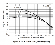
With some more knowledge, some parameters can be deduced from looking at curve plots in those datasheets, and they're just approximations, but this requires knowing how to interpret that properly.
I know there are going to be many who will again and again speak against the 3055 specifically, saying it's not worth the effort, it's a waste of time and efforts, but again, I know I'm not the only one out there looking to use that part, so there is no point in spoiling the fun by flaming. Some of us diyers do want to make use of that part, so get used to it
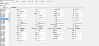
I have done several things towards tweaking a model, including collecting all parameters from multiple 3055 models and shoved them into a spreadsheet, for easy and quick comparison at a glance, made a few spice sim test rigs to see how the models perform, and gathered more datasheets to hopefully get a wider array of parameters and be able to come up with a rough average/typical set of values.
I know there are many incarnations of the 3055, and many aren't even worth bothering with. Especially the fakes and I think we can just ignore the old types.
Most of the newly manufactured 3055s have the bulk of their specs in datasheets the same or very similar, so it's not much of a stretch to extract something that's typical and mostly representative. There is no need for multiple models, it can be one that's most representative and works.
Many of the models I have on hand have parameters left at the spice default, and that's not always too accurate.
Doing this for the 3055 can be informative and instructive, so then tweaking more models can be done in the same way.
At the moment I'm trying to come up with the parameter values that make the model behave as close as possible like shown in the datasheets, regarding the beta/hfe with a test rig that plots Ic/Ib, with the possibility of stepping the temperature as well.
I'm building a new model from scratch, and tweaking parms one at a time, comparing with the other existing models.
And I'm using some parms values for some of them that are somewhat known to be ok, like for example the VAF=150, which was deemed to be fairly close enough to representative.
I've seen the BF parm in models vary from 73 to 360. Now that can't be all correct. For one thing, no 3055 has that much beta anyway, as the datasheets all spec it at 20-70, so I think anything above about 100 can't be too realistic.
However, having compared that with the curves in the datasheets, I find that a value of 110 for BF seems rather fitting.
Then I looked at XTB and IKF.
In the various models, many simply omit XTB, which makes it default to 0, and that just can't be right, as the beta would be constant and nothing like the real thing.
And IKF, sometimes omitted as well, varies between 0.25 and over 4, which also can't be quite right, and those models just can't be behaving like the real thing.
To bring the behavior closer to what's on the curves (beta/Ic), including temperature behavior, I ended up with values of 1.3 for XTB, and 2.66 for IKF.
Then I looked at the capacitance, CJC and CJE. Although I haven't got any spice test rigs yet to verify this, and the datasheets don't all provide this info, or only a part of it. The BC junction capacitance, would seem to be somewhere in the 500-700p range, max, and models have from 212p to 1n, if specified (default=0).
Since there are models using values roughly in the lower middle of that range, I settled on 300p.
And the CJE wildly ranges in models from 415p to more than 90n. Not being provided in datasheets at all, it's a wild (hopefully somewhat educated) guess that the high values, anything above 1n, would be wrong, and so I settled on 500p.
That's a few parms already, but nothing close to the whole set.
How about a new thread for this?
Perhaps it would be a good thing to do to start a new thread just for that.
At the moment, I'm still trying to figure out how to properly tweak a 2N3055 model, and I'm sure I will again trigger some flaming about it, but a thread can remain general about any model type, but that is where I would start.
I have several 3055 based circuits in the works and the models really need help to get it right.
A dedicated thread would of course be open to any models and could be a place to exchange little test rigs for simulation to verify model parameters.
No matter how much I read stuff over and over about this, starting by Bob C's chapter in his book, and trying to dig into datasheets for pertinent info, I always fall way short of having all the needed info.
The datasheets are just too slim and really don't give all needed details.
With some more knowledge, some parameters can be deduced from looking at curve plots in those datasheets, and they're just approximations, but this requires knowing how to interpret that properly.
I know there are going to be many who will again and again speak against the 3055 specifically, saying it's not worth the effort, it's a waste of time and efforts, but again, I know I'm not the only one out there looking to use that part, so there is no point in spoiling the fun by flaming. Some of us diyers do want to make use of that part, so get used to it
I have done several things towards tweaking a model, including collecting all parameters from multiple 3055 models and shoved them into a spreadsheet, for easy and quick comparison at a glance, made a few spice sim test rigs to see how the models perform, and gathered more datasheets to hopefully get a wider array of parameters and be able to come up with a rough average/typical set of values.
I know there are many incarnations of the 3055, and many aren't even worth bothering with. Especially the fakes and I think we can just ignore the old types.
Most of the newly manufactured 3055s have the bulk of their specs in datasheets the same or very similar, so it's not much of a stretch to extract something that's typical and mostly representative. There is no need for multiple models, it can be one that's most representative and works.
Many of the models I have on hand have parameters left at the spice default, and that's not always too accurate.
Doing this for the 3055 can be informative and instructive, so then tweaking more models can be done in the same way.
At the moment I'm trying to come up with the parameter values that make the model behave as close as possible like shown in the datasheets, regarding the beta/hfe with a test rig that plots Ic/Ib, with the possibility of stepping the temperature as well.
I'm building a new model from scratch, and tweaking parms one at a time, comparing with the other existing models.
And I'm using some parms values for some of them that are somewhat known to be ok, like for example the VAF=150, which was deemed to be fairly close enough to representative.
I've seen the BF parm in models vary from 73 to 360. Now that can't be all correct. For one thing, no 3055 has that much beta anyway, as the datasheets all spec it at 20-70, so I think anything above about 100 can't be too realistic.
However, having compared that with the curves in the datasheets, I find that a value of 110 for BF seems rather fitting.
Then I looked at XTB and IKF.
In the various models, many simply omit XTB, which makes it default to 0, and that just can't be right, as the beta would be constant and nothing like the real thing.
And IKF, sometimes omitted as well, varies between 0.25 and over 4, which also can't be quite right, and those models just can't be behaving like the real thing.
To bring the behavior closer to what's on the curves (beta/Ic), including temperature behavior, I ended up with values of 1.3 for XTB, and 2.66 for IKF.
Then I looked at the capacitance, CJC and CJE. Although I haven't got any spice test rigs yet to verify this, and the datasheets don't all provide this info, or only a part of it. The BC junction capacitance, would seem to be somewhere in the 500-700p range, max, and models have from 212p to 1n, if specified (default=0).
Since there are models using values roughly in the lower middle of that range, I settled on 300p.
And the CJE wildly ranges in models from 415p to more than 90n. Not being provided in datasheets at all, it's a wild (hopefully somewhat educated) guess that the high values, anything above 1n, would be wrong, and so I settled on 500p.
That's a few parms already, but nothing close to the whole set.
How about a new thread for this?
I hope I didn't say anything that seemed like flaming, I just wanted to make sure you really wanted to do it. If you want to do it anyways, then I assume you have good reasons. I'll help.
Cje IS OFTEN VERY LARGE. It's true. 500pF is too small for a lot of transistors - impossibly small for any powerful BJT. Think about it, Vbe rarely varies by more than 100mV in most circuits. There often isn't enough signal across Cje to make it's large capacitance obvious. You can figure out Cje by matching the Ft curve in the datasheet, luckily.
Ise models the upward slope of Hfe. If your transistor has low gain at low Ic, then you need to use Ise to model it. Ikf is WYSIWYG. You can change Nk to increase the steepness of the Hfe drop, but usually the quasi-saturation parameters are the correct way to do this.
Ask a mod to split our posts into a new thread.
Last edited:
I hope I didn't say anything that seemed like flaming, I just wanted to make sure you really wanted to do it. If you want to do it anyways, then I assume you have good reasons. I'll help.
I wasn't from you that I felt flaming. Actually I think quite some time ago we've exchanged about getting something together about models, so we could all have good ones to use and share.
When it comes to the 3055, I've had exchanges with many others who are really interested, and those are easy and cheap to get in some part of the world where other new devices are either too hard to get or far too expensive. So why not?
Plus it's fun and a challenge to try to get more out of those things than we were ever able to do long ago.
Cje IS OFTEN VERY LARGE. It's true. 500pF is too small for a lot of transistors - impossibly small for any powerful BJT. Think about it, Vbe rarely varies by more than 100mV in most circuits. There often isn't enough signal across Cje to make it's large capacitance obvious.
I figured whatever the cje value may be, it wouldn't have too much influence anyway, but better try to get a value that's more correct, so we have valid models.
This may have a small influence on thd anyway.
So I suppose my choice for 500p is too low. But in all the models I have, although there is a value over 90n for one of them, which seemed far too high to me, the majority of the models are more in the 500-600p range, even though one of them goes as low as 415p. So they would almost all be wrong there.
You can figure out Cje by matching the Ft curve in the datasheet, luckily.
That I'd like to know how.
Ise models the upward slope of Hfe. If your transistor has low gain at low Ic, then you need to use Ise to model it.
ISE is supposed to be the leakage saturation current for the BE junction, as far as I understand, but I don't know how to get the right value. It defaults to 0. Not good.
Ikf is WYSIWYG.
That's pretty much how I picked a value. Seeing the rather wide range in the various models, they just can't all be right, and once a curve is visualized, matching it to what's in a datasheet, visually, can point to a fair value.
I looked at value of beta at 1A on the 25C curve, which was at something like 90, while keeping an eye on where the beta ends up at 10A, which is a little over 20 or so. I look at several datasheets and guess-timate a rough typical value as a base.
I can also see how for example the modpex models (not so good), that they state are supposed to be matching the datasheets, are mostly not doing so. Some values for some parms may be in the ballpark, but many aren't even close.
You can change Nk to increase the steepness of the Hfe drop, but usually the quasi-saturation parameters are the correct way to do this.
What's Nk?
I need to get more understanding of this.
The Nk parameter is an exponent or something in the equation, normally it's 0.5 and it goes up to 1. Too high and I've found you can get convergence problems. I haven't really found it very useful after I figured out the quasi-saturation parameters. I would leave it alone for now. Choose Ikf to position the Hfe peak in about the right place, but don't worry about getting the cliff part perfect until you understand the quasi-saturation parameters.
Modeling Ft is hard without an appropriate modeling jig. But once you have it you can just change Cje until the low-current Ft is right. Someone who's very handy with a calculator could perhaps calculate a starting value based on the datasheet, but that would take just as long for most of us.
Another thing you can do is use the capacitance meter on your DMM to measure Cje and Cjc (these parameters represent the 0V junction capacitances, so will be different from what is on the datasheet). IIRC I used a 100pF capacitor in series with the junction capacitance to prevent the DMM output voltage from changing the junction capacitance I was intending to measure. Then you have to calculate the junction capacitance based on the measurement.
Ise is typically in the fA to pA range. When you are experimenting with a new parameter you need to start with say 1f, then jump to 1k and try to identify what changed. Then keep going back and forth between high and low numbers until you've found the applicable range for the parameter. It's faster than asking on a forum and waiting a day for someone who knows about it to respond.
Ultimately if you hesitate to experiment and try to do everything "by the book", you will end up not getting a visceral understanding of the parameters and modeling process. If you at least know what each parameter does, you can usually figure out how to adjust it by experimentation.
The Nk parameter is an exponent or something in the equation, normally it's 0.5 and it goes up to 1.
I've never seen that parm anywhere in any models before, and have never come across it in any doc. So it's really new to me. I didn't know it existed.
Choose Ikf to position the Hfe peak in about the right place, but don't worry about getting the cliff part perfect until you understand the quasi-saturation parameters.
There are interactions between parms that need to be understood. So I need to go through all this stuff.
I picked IKF (for 3055) at 2.66 because it placed the point that I picked as a reference in the right place. That was the beta at about 90 for Ic at 1A, which I figured was about right, after comparing datasheets.
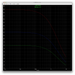
To illustrate my result, I'm posting a snapshot of the plot from my test rig, where there are 3 curves for 3 temperatures at -55C, 25C and 150C, which were available curves in datasheets.
That's for a new model in development, that only has a few defined parms so far (3055).
The blue curve is the 25C temp curve, and it does have the crossing very close to 90 beta for Ic at 1A.
Was that wrong? Other interaction would move this I suppose.
Here is what that embryo of model looks like:
.model 2N3055 NPN ( BF=110 IKF=2.66 XTB=1.3 VAF=150 CJC=300p CJE=500p )
Not much there, but many parms have defaults, so it actually more than it looks, although largely wrong.
Modeling Ft is hard without an appropriate modeling jig. But once you have it you can just change Cje until the low-current Ft is right.
That rig needs to be made then. It belongs in the bag of tricks for the model builder (tweaker).
Someone who's very handy with a calculator could perhaps calculate a starting value based on the datasheet, but that would take just as long for most of us.
For me too, and I would forget how to do it in no time, so the next time I'd have to learn it all over again.
Something automatic (mostly) needs to be built, so all the intelligence behind it is put into it and doesn't require being recalled every time it's needed.
And of course that has to be usable for any device, to make any model as needed.
In that beta-vs-Ic test rig that I'm using now, I made the NPN device called DUT, with the temp parm, so I can swap to any model easily and quickly. With the spice statements prepared, it's easy to rem out what's not needed at the moment and run exactly what's needed. Hopefully not requiring any brain work the next time it's used.
Another thing you can do is use the capacitance meter on your DMM to measure Cje and Cjc (these parameters represent the 0V junction capacitances, so will be different from what is on the datasheet).
Unfortunately I'm not that well equipped. I only have basic stuff, and I do have a DMM but too simple without those features. All I have is voltage, currents, resistance and it can measure a junction voltage, nothing more.
IIRC I used a 100pF capacitor in series with the junction capacitance to prevent the DMM output voltage from changing the junction capacitance I was intending to measure. Then you have to calculate the junction capacitance based on the measurement.
Clever
But the DMM functions needed I lack.
The value of the 100p would have to be known. That is, it's real value, not the one marked on it.
I do have a separate capacitor meter (cheap), and its lowest range is 200p, but I have no idea how it does its measuring. Could that suffice?
Ise is typically in the fA to pA range.
The models I have are spread from about 33p to 1n. Pretty wide range, being for the same device!
When you are experimenting with a new parameter you need to start with say 1f, then jump to 1k and try to identify what changed. Then keep going back and forth between high and low numbers until you've found the applicable range for the parameter. It's faster than asking on a forum and waiting a day for someone who knows about it to respond.
Except I don't know how to test for it.
Ultimately if you hesitate to experiment and try to do everything "by the book", you will end up not getting a visceral understanding of the parameters and modeling process. If you at least know what each parameter does, you can usually figure out how to adjust it by experimentation.
I do try to experiment, but for most things, I have no idea what experiment is to be made.
I'm making more test rigs as I go along, but so far they're the simplest ones.
Attachments
I tried using that cheap capacitance meter on one of my old 3055s.
Can this be a trusted method?
Anyway, what I got is 130p for BC and 180p for BE, however, swapping the polarity gives exactly double those numbers for each junction.
Does this sound about right?
If this is valid, then it's on the low end of the spec range. It wouldn't be bad.
But for a model parameter, it would be better to go by the datasheet, with a typical spec value, as this actual measurement would just be one possible example among many and there would be variations, potentially fairly large ones.
I'm just realizing one thing that must have an impact on what we measure from devices for capacitance.
Along with CJC and CJE, there is also XCJC, and I would assume an actual measurement would be XCJC and not CJC.
With a meter like this, I have no idea how it does its measurement and how much current and voltage is used.
Along with CJC and CJE, there is also XCJC, and I would assume an actual measurement would be XCJC and not CJC.
With a meter like this, I have no idea how it does its measurement and how much current and voltage is used.
Choose Ikf to position the Hfe peak in about the right place, but don't worry about getting the cliff part perfect until you understand the quasi-saturation parameters.
Would this quasi-saturation have anything to do with the IS parm?
Somewhere along this thread I do think andy_c has given a few tips on how to extract parameters according to the datasheet, there was a mention of a digitizer app. Converts the graph in the datasheet into numerical figure so the simulator can read it.
Me on the other hand I just download and install different simulation package and check out the models that comes with it and when I found models that could be useful to me I just rummage to the library folder, copy the files and paste it to Notepad++ [converts them into ANSI]. Most models that I look for are in Microcap, but Notepad++ cannot decrypt them so I just open the file via the default program and manually hand code them in Notepad++ [Notepad++ is a programmers tool a powerful decrypting and encrypting app]
Now this makes me raise a question;
Is the order of data entry crucial to the simulator? [LTSpice] or can I just copy the whole inputted data, whatever parameter is there and whichever goes first, will this work fine with LTSpice?
This is how Microcap do it..maybe not so accurate for use with LTSpice but should be good enough as a start [I always treat simulation results with a margin of error]
Sa muli,
Albert
Me on the other hand I just download and install different simulation package and check out the models that comes with it and when I found models that could be useful to me I just rummage to the library folder, copy the files and paste it to Notepad++ [converts them into ANSI]. Most models that I look for are in Microcap, but Notepad++ cannot decrypt them so I just open the file via the default program and manually hand code them in Notepad++ [Notepad++ is a programmers tool a powerful decrypting and encrypting app]
Now this makes me raise a question;
Is the order of data entry crucial to the simulator? [LTSpice] or can I just copy the whole inputted data, whatever parameter is there and whichever goes first, will this work fine with LTSpice?
This is how Microcap do it..maybe not so accurate for use with LTSpice but should be good enough as a start [I always treat simulation results with a margin of error
]Sa muli,
Albert
Attachments
Last edited:
Here is a rig you can use for Hfe and Vbe. It sweeps Ic. Place your model on the schematic with a .op statement and then you can change parameters quickly. You will need to change the name of the transistor to your model name even though your model won't show up in the model menu this way.
Attachments
Somewhere along this thread I do think andy_c has given a few tips on how to extract parameters according to the datasheet, there was a mention of a digitizer app. Converts the graph in the datasheet into numerical figure so the simulator can read it.
Seems interesting. I'll have to keep digging. May be useful, if I can use it.
Me on the other hand I just download and install different simulation package and check out the models that comes with it and when I found models that could be useful to me I just rummage to the library folder, copy the files and paste it to Notepad++ [converts them into ANSI]. Most models that I look for are in Microcap, but Notepad++ cannot decrypt them so I just open the file via the default program and manually hand code them in Notepad++ [Notepad++ is a programmers tool a powerful decrypting and encrypting app]
Totally windoze centric, which I can't do, since I'm a mac head.
Now this makes me raise a question;
Is the order of data entry crucial to the simulator? [LTSpice] or can I just copy the whole inputted data, whatever parameter is there and whichever goes first, will this work fine with LTSpice?
I've been wondering myself for quite some time. Although I see parameters in models are not all in the same order, so if there is something to it, I suspect it would apply to parms in the same "group".
I came across a model that repeated twice the same parameter, which was confusing, but I figured that had to be a mistake. However, this brings up an other question: when parms are repeated (with different values), which one has precedence?
You may want to check TINA I think it had a 3055/2955 model, could not remember though if it was a 2N or TIP models.
I remembered having looked into that before. I just checked again, but as I thought, it's all windoze centric, so nothing there for me (mac head).
Here is a rig you can use for Hfe and Vbe. It sweeps Ic. Place your model on the schematic with a .op statement and then you can change parameters quickly.
Thanks, that'll help. I was trying to come up with something like that, but I'm sure yours will work better.
You will need to change the name of the transistor to your model name even though your model won't show up in the model menu this way.
Well, I use ako: to point to models, which is a quick way to switch them.
No model menu for me on mac. Pitiful how the mac version of ltspice is so crippled, and now it doesn't even look like we'll get the newer one for it, as usual, the mac users are 3rd grade people who get dismissed.
I'm trying to make a test rig for Ft. I know we can see something in the log when running an .op, but it doesn't give a plot, and I'm wondering how reliable that result is, as so far the result given is totally silly.
The rig I posted actually can be used for Ft. Look at the commented text. You may need to alter the .meas statement to switch between Q1 and Q2.
OK thanks. I hadn't opened it yet, I'm going to be out for a while so I'll look at this later on. Should be good
The order of parameters is not important, IIRC if there are redundant parameters the first one is used.
Well that answers a question. Good to know, thanks.
I remembered having looked into that before. I just checked again, but as I thought, it's all windoze centric, so nothing there for me (mac head).
Didn't realize that...


If your have a pdf reader perhaps the attached file could be of use to you.
Attachments
Didn't realize that...
If your have a pdf reader perhaps the attached file could be of use to you.
Already have that. It's among all those things I've gathered in my quest for better models.
I've been playing with the jig and introduced a few more parameters into the model being built.
When IS was introduced, it had a side effect that affects adversely the highest temperature operation, in this case, the 150C curve, with a spike at the lowest Ic going upwards in gain.
I tweaked ISE, ISC and IS, and re-tweaked IKF and XTB, looking to get the curves closer to the datasheet's, but I'm only roughly in the ballpark.
Especially with that upward going curve for 150C at the low values..
The parms interact and when adjusting for something, we get other effects somewhere else.
Not an easy thing to do.
I even re-adjusted BF a bit, upwards, because of the effects from the others.
Right now that model has this:
.model 2N3055 NPN ( IS=5p ISE=9p ISC=5p BF=120 IKF=2.7 XTB=1.4 VAF=150 CJC=300p CJE=500p )
Of course all the parms with defaults are there, even if not present, so the actual modeling is more than it looks from that short line.
I haven't even looked at other things yet. I'm not quite close enough with this yet.
At least something is coming together, but still lots more to do.
I measured a couple of my 3055s for beta, and they're at about 130 for Ib=1mA, and droop to about 70 for Ib=10mA. They should droop down to something like 15-20 when Ic is at something like 10A or so, but I obviously can't test that.
It's mostly like the datasheet, sort of.
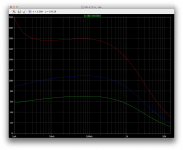
Attachments
- Home
- Design & Build
- Software Tools
- Spice simulation