MI,
What supply voltage are you using? The Bipolar caps seem to be limited to 50v and the panasonic range only have a projected life of 2000 hrs.
I will be using two standard electrolytics back to back.
I use +5/-5v for the 393 comparator, which can take + input above Vcc. I have some Nichicon 47uf @100vDC. Looking at using 25-35 vDC versions. I'm not worried about the ratings on the bi-polars, the ripple current is very low. I checked this on LTSpice, which I finally started to learn.
I have been doing some more testing with the filters, on spice I found that a 2 pole filter with 100k/10uf 1st stage and 100k/5uf 2nd stage gave much better performance than 100k/47uf single pole. Response time with the breadboard was also better.
This is interesting.
I was looking at pcb mounted relays but may go for separate relays in case of replacement.
If you are going to use relays, check some of the threads about which to use.
Later,
MI
Please disregard my prior schemes, there are some big discrepancies and issues in the drawings.
The following updated scheme attachment is what I have working ATM. Fewer parts as well. Not much to it. Soft-start and DC protection by way of mains kill..
Cheers
S
View attachment SOFT_DCPROT.pdf
The following updated scheme attachment is what I have working ATM. Fewer parts as well. Not much to it. Soft-start and DC protection by way of mains kill..
Cheers
S
View attachment SOFT_DCPROT.pdf
synonymous,
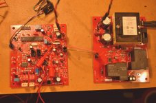
I didn't think about looking at dual led opto couplers, nice move. I went with my detector as last posted. At least my MCU board is working, I feel most relieved. I'm not going to show anymore here, but one last (not very good) image, don't want to keep hijacking oldjack's thread. By the way what OS are you booting into on your Raspberry Pi? Great I got some, like I need something else to work on.")
Later,
Mad
I didn't think about looking at dual led opto couplers, nice move. I went with my detector as last posted. At least my MCU board is working, I feel most relieved. I'm not going to show anymore here, but one last (not very good) image, don't want to keep hijacking oldjack's thread. By the way what OS are you booting into on your Raspberry Pi? Great I got some, like I need something else to work on.
Later,
Mad
Attachments
synonymous,
I didn't think about looking at dual led opto couplers, nice move. I went with my detector as last posted. At least my MCU board is working, I feel most relieved. I'm not going to show anymore here, but one last (not very good) image, don't want to keep hijacking oldjack's thread. By the way what OS are you booting into on your Raspberry Pi? Great I got some, like I need something else to work on.
Later,
Mad
It's always nice to have something work after lots and lots of work heh.
I have a few SD cards that I use to try different systems on the RPI. At the moment, I am using mostly volumio and spotify on it. The interface is totally crummy if you ask me, but it works and the 320kbs vorbis is sounding very good. I like being able to listen to anything and spotify does that well. What else is nice is that the driver for the DAC uses a pin on the PI gpio to unmute itself, and that same pin I use to power up my amp. The config is super simple to get the whole thing up and running. Took lots and lots of work and trials to get here, but here it is lol. Let me know if you'd like a board for a PCM5122 DAC, I've got some extras. The PCM and one ferrite bead are the only SMD parts involved and are super simple to do with low temp solder paste.
Cheers
s
Last edited:
Please disregard my prior schemes, there are some big discrepancies and issues in the drawings.
The following updated scheme attachment is what I have working ATM. Fewer parts as well. Not much to it. Soft-start and DC protection by way of mains kill..
Cheers
S
View attachment 686859
I've been breadboarding a similar DC detection circuit to what you are showing here. I've been getting some delay in activation of the DC detection circuit at lower voltages. Have you experienced anything like this?
I've been breadboarding a similar DC detection circuit to what you are showing here. I've been getting some delay in activation of the DC detection circuit at lower voltages. Have you experienced anything like this?
Your mileage will most certainly vary
I am using 50v rails. Anything more or less will need some adjustments and attention to the wattage across the resistors in the circuit. The trip frequencies in my live testing were taken with the DAC at full output and no attenuator on the amp, no load. In real world use, the output signal will near certainly never ever be near this test. One could aim for a much faster response using a lower capacitance, or using a lower resistance, depending on desires and parts. My DAC will output a 1hz signal, but the speakers run out of travel well before full output, so, like I said, you can aim for a faster response real-world trip setting, lowering the resistance of the sense circuit, paying attention to the wattage of the resistors. I am using a Darlington type opto, so keep that in mind as well. This circuit is very simple and will run out of sensitivity at a low enough DC offset, however, the goal is to protect from a failed output transistor shorting to the rail, which is in practice, even rare for my amp design. It will basically never happen, but the mechanism is there in case. Additionally, my system cycles itself on and off based on activity, so I can sleep confidently and ignorant of it, waking up to a cold amp.
Let us know your findings/results
I found any DC up around 5V+ would give an instant trigger. I like the trigger point to be under 2V if possible in my detection circuits. I found a 0.5 - 1 second delay at these voltages. I was also using a photodarlington device, LTV-8141.
Want to share your scheme?
What are you triggering?
I'm just toggling a latching relay.
I want to trigger a solid state relay and signal a microcontroller to shut down from it. I've attached a quick schematic but I've only tested the DC detection portion so far.
Looks similar
Remember also that DC will come in the form of a hard edge, so, mostly what you are working with is keeping from triggering in your normal sinewave listening spectrum.
We experiment with tube hybrid design amplifiers so DC can creep up on the output (tube heater failure) or instantly skyrocket. Our present DC detection design triggers below 8Hz at 1.6 - 1.8VDC and is very reliable, but it requires rail voltage from the amplifiers main power supply. I began looking at opto-isolator design detection to eliminate the need for rail voltages.
Once upon a time I was looking at a project that used a PIC controller to sense the line signal to activate power to an amp. I didn't get past entertaining ideas about it, however, It did look interesting in that PIC controllers have an analog input that one can measure voltages at. I thought about both using it as it was and also potentially using it to compare voltages. I figured that the end all to monitoring an output would be to compare it to an input. Say that the output is deviated from the input signal wave, then activate a protection circuit. This way, there would be nearly no delay at all in any protection. I don't have the programming know how or knowledge of how to create those windows of comparison, but I would imagine if you have the curiosity, you could have the end all solution.
S
S
The issue I see with a protection scheme like that is you would be connecting your analog ground and digital grounds together. If this is in a two channel amplifier, you would inadvertently be tying both channels analog grounds together through the digital ground, setting you up for a ground loop issue. In our present protection schemes we use an Arduino based microcontroller but every connection to the actual amplifier is done through an optoisolator making it very simple to install in any amplifier without worry of extra noise due to grounding.
Programming for Arduino based controllers is much easier than PIC. It's all open source and there are loads of examples to control just about anything on the internet. PIC software seems to always be kept a secret with little free support.
Programming for Arduino based controllers is much easier than PIC. It's all open source and there are loads of examples to control just about anything on the internet. PIC software seems to always be kept a secret with little free support.
Attachments
Looks very fine! Are you selling boards or d´can you provide Gerbers an a schematic?
Hello everyone
I realized a DC protection with mosfets relay that gives me complete satisfaction. the input is equipped with a second order filter for very low frequencies that could be assimilated to a DC voltage, an adjustable DC detection of +/-0.6V to +/-1.5V and an adjustable delay and with some changes in resistance values the operating voltage is +15V to +50V.
- Status
- This old topic is closed. If you want to reopen this topic, contact a moderator using the "Report Post" button.
- Home
- Amplifiers
- Solid State
- Speaker Protection Using Optoisolator