MI
I probably misunderstood your question.
The low pass filter is designed to prevent false trips from low frequency signals.
The comparator trip level when I said a maximum of 17v; it meant that any signal above 17v will send one of the opamp outputs high and close the output relays whatever the setting of the trip level, but I would probably set trip level at around 1v. If it is set too low I think there could be false triggers along with the problem of the relays repeatedly switching on and off.
Not sure what you meant by subsonic?
DC offset
oldjack
Subsonic as subsonic filter for albums normally below 20hz. I should have done better at separating the AC(audio) from DC components in my messages. Because my design will use a MCU (atmel 328P) I could/can use software for false trips. I might try my prototype with the cannons in 1812 overture, to see what happens. I do want my design to trip if there is a large subsonic component in the audio.
MI
MI
I probably misunderstood your question.
The low pass filter is designed to prevent false trips from low frequency signals.
The comparator trip level when I said a maximum of 17v; it meant that any signal above 17v will send one of the opamp outputs high and close the output relays whatever the setting of the trip level, but I would probably set trip level at around 1v. If it is set too low I think there could be false triggers along with the problem of the relays repeatedly switching on and off.
Not sure what you meant by subsonic?
oldjack
Subsonic as subsonic filter for albums normally below 20hz. I should have done better at separating the AC(audio) from DC components in my messages. Because my design will use a MCU (atmel 328P) I could/can use software for false trips. I might try my prototype with the cannons in 1812 overture, to see what happens. I do want my design to trip if there is a large subsonic component in the audio.
MI
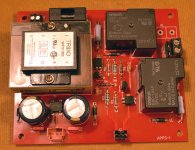
Is this a separate power supply for the relays and protection circuit?
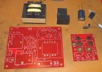
The boards take up quite a lot of space. My problem is available space in the casings.
I have one case with all the amps and attenuator power supplies and another case with the filter, attenuator and amplifiers. Both cases are full so my next build will have to have larger cases.
I thought about trying surface mount components for the protection circuit but might have problems with the filter capacitors.
Did you make the boards yourself?
Is this a separate power supply for the relays and protection circuit?
Yes, it powers the controller board and speaker switch.
The boards take up quite a lot of space. My problem is available space in the casings.
I made this separate board design, so P/S can mount by Amp power supply, controller can be away from P/S and speaker switch mounts on binding post. All the boards can be installed in separate box for external protection on existing Amps.
Did you make the boards yourself?
No, ordered from PCBway.
MI
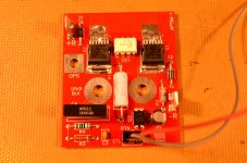
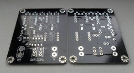
Soft start options
I finished one of my power supply/soft-start boards. I have R1 pads for leads running to terminal board to the side, so I can use inrush limiter or power resistor, if it fails badly, won't burn the board. Will build speaker switch next. Still need to finish MCU design and software.
Later,
MI
PS Who's taking all the 2.5 mohm mosfets?
Attachments
Loads o fun aye..
Madinventor, take a look at the smaller PCB mount switching supplies. Digikey has some tiny ones in the 200mA range, and RECOM has some in the 2A range. I'm using a RECOM for powering a RPI3 and my start and protection scheme..
After some tinkering and testing, the following is all that I have found to be needed..
I have kept the MOSFET output relays as an option and are all comprised of SMD parts that hide their ugliness on the bottom of the PCB board. I intend to omit the MOSFET relays in that I don't find it necessary to either/both mute my soft start powerup (its quiet), nor to protect from DC at the output, given that I will be using speakers capable of 1000w short term and that the power is disconnected in one second and gone in less than 2 seconds. It's there nevertheless out of the way as an option..My DC detect duration is long because I have discovered that my DAC will output a strong 1HZ signal and my amp is DC coupled, hence the 1 second trip time. One could play with the values to get a quicker trip time. Also, where I show the "RUN" signal, one could easily replace it with a low voltage power switch running from the same 5v supply, perhaps altering the zener in the delay circuit as well. This circuit will need a 5v supply using these relays, Digikey has some small SIP switching supplies that can power this circuit for under $10. I've started some time ago intending on using PIC or other MCU, however, even those that I asked to help program it recommended doing it otherwise. It's down to so simple now that even the rest of the PI stuff complexity is gone. I've got a UPS with a real power button and real power cycling and filesafe powerloss functionality for the PI as well that will actually fit onto the same PCB as the DAC does. No MCU.
I'll probably make this into something and freely collaborate if there's some interest.
S
View attachment sstartdcprot.pdf
Forgive missing 3d MOSFET prints
interesting
Hello synonymous
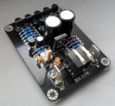
Let me guess you use a toaster oven to mount the Mosfets. Interesting circuit, my setup will watch DC offset, sink temperature and bias. I'm pretty much stuck on this coarse having bought everything but the controller PCB board. Here is the speaker switch, I just finished.
Later MI
Hello synonymous
Let me guess you use a toaster oven to mount the Mosfets. Interesting circuit, my setup will watch DC offset, sink temperature and bias. I'm pretty much stuck on this coarse having bought everything but the controller PCB board. Here is the speaker switch, I just finished.
Later MI
Attachments
HAHA
No toaster
I've only done SMD just a few times and all it took was some low-temp solder paste to make me into a pro. Depending on the job, I'll either do a hot plate on a slab of aluminum, or use the heat gun. All the VOM are out of stock, so I'm going without the output relay as it is. In the end, after some old LMOSFETS I have on the shelf are used up, I intend to use double-die laterals and in this case, it'd most likely be beyond my lifetime when they let go. I just don't want to start a fire.
Oldjack -
If you are looking for slightly simpler circuits, Bonsai (past member here) designed and used this one successfully in his Ovation amplifier, which started the DIY SSR trend here some years ago, when the speaker relay failed to open and break the current, so a treasured loudspeaker bit the dust.
Good article and design discussion too: http://hifisonix.com/wordpress/wp-content/uploads/2012/08/Speaker-Relay-V1.03.pdf
the DIY SSR trend here some years ago, when the speaker relay failed to open and break the current, so a treasured loudspeaker bit the dust.
I'm sold on SSR. Future incarnations of my system will have SSR for mains at some point..
Mad Inventor,
What mains fuse is that youre using? Looks 5mx20m, but where did you get the protective shroud for it?
I've done some real world tests this morning and both adjusted the scheme and values associated. In production, I am going to start at 10k for my RO in my scheme, set at ~ 2Hz trip. Keep in mind that your mileage will vary depending on your amplifier and input. The RO resistor you will have to calculate for wattage as well. I am able to get away with using my surplus of 600mW resistors at values 6.8k and over. Lower values may need higher wattage in ones setup. My results were achieved using my own DC coupled PCM5122 DAC and amp, full gain, no load. Worst case.
Cheers
Updated..
View attachment SSPROTMAY18.pdf
I'm sold on SSR. Future incarnations of my system will have SSR for mains at some point..
I started my quest after reading this message by Micheal Bean http://www.diyaudio.com/forums/solid-state/191449-output-relays-3.html#post2618977, sometime in 2014, before I joined in 2015, this got me started on my amp protection project.
Mad Inventor,
What mains fuse is that youre using? Looks 5mx20m, but where did you get the protective shroud for it?
I got the PCB holders (5x20) from Newark, but others Digi-Key, Mouser have some also.
Later,
MI
Ian, yes interesting article.
My amps are not very high outputs, LF 60w/channel, MF 35w/channel and HF 30w/channel so I am still going for standard relays with this first design.
Building it on a breadboard at the moment, not sure how it will perform at very low frequencies; on spice it is okay down to 0.5hz provided the dc is above approx 3v.
For very low dc at this frequency the opamps would cycle on/off.
I also have a dedicated transistor for each relay coil.
Following Madi's comments I will build everything into a separate box with power supplied from the main amp case as I have 6 regulated power supplies available for the front end filters and attenuators/pic (+/-15v, +/-5v x 2).
Hello everyone
I realized a DC protection with mosfets relay that gives me complete satisfaction. the input is equipped with a second order filter for very low frequencies that could be assimilated to a DC voltage, an adjustable DC detection of +/-0.6V to +/-1.5V and an adjustable delay and with some changes in resistance values the operating voltage is +15V to +50V.
I realized a DC protection with mosfets relay that gives me complete satisfaction. the input is equipped with a second order filter for very low frequencies that could be assimilated to a DC voltage, an adjustable DC detection of +/-0.6V to +/-1.5V and an adjustable delay and with some changes in resistance values the operating voltage is +15V to +50V.
Attachments
Last edited:
Hello everyone
I realized a DC protection with mosfets relay that gives me complete satisfaction. the input is equipped with a second order filter for very low frequencies that could be assimilated to a DC voltage, an adjustable DC detection of +/-0.6V to +/-1.5V and an adjustable delay and with some changes in resistance values the operating voltage is +15V to +50V.
Are documentations for share?
Have you any spare pcb?
Hello everyone
I realized a DC protection with mosfets relay that gives me complete satisfaction. the input is equipped with a second order filter for very low frequencies that could be assimilated to a DC voltage, an adjustable DC detection of +/-0.6V to +/-1.5V and an adjustable delay and with some changes in resistance values the operating voltage is +15V to +50V.
Project16
Where did you get your PCB? Maybe I should of gone with black, they would have blended in with the black chassis sitting on the speaker post, gone invisible.
MI
Hello All
Yes, I can share schematics and the list of materials but it has to be clean and well documented. I have some pcb of available (2oz).Are documentations for share?
Have you any spare pcb?
I made my pcb at 'FirstPCB'.Project16
Where did you get your PCB? Maybe I should of gone with black, they would have blended in with the black chassis sitting on the speaker post, gone invisible.
MI
Maybe this is good solution for you?
that's for 6 ch or 3 stereo
6 CH Turn On Delay & DC Speaker Protection with Thermal Switch Input W.V 9/18VAC | eBay
that's for 4 ch or 2 stereo
4 CH Turn On Delay & DC Speaker Protection with Thermal Switch Input W.V 9/18VAC | eBay
that's for 6 ch or 3 stereo
6 CH Turn On Delay & DC Speaker Protection with Thermal Switch Input W.V 9/18VAC | eBay
that's for 4 ch or 2 stereo
4 CH Turn On Delay & DC Speaker Protection with Thermal Switch Input W.V 9/18VAC | eBay
- Status
- This old topic is closed. If you want to reopen this topic, contact a moderator using the "Report Post" button.
- Home
- Amplifiers
- Solid State
- Speaker Protection Using Optoisolator