Hi Gannaji/Tromperie, long reply so sorry. Hope there is not too much detail.
OK, from left to right.
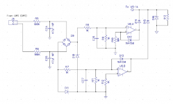
a) from the L or R power transformer a discrete bridge rectifier charges C3 (3u3) through R17 (3k3) and C3 discharges through R15 (1k) giving around 15mA average for the LED of opto coupler U1 (4N37). The LED current falls to <<1mA in about 5mS after the transformer loses its mains input and the opto transistor turns off. In turn the window comparator reference is forced high forcing the lower output high which turns the mosfet relay OFF (workings explained below).
b) Powerup Reset U1a output is forced low from power on until until C2 (33u) is charged to 0V through R6 (100k), taking about 3 seconds. R12 provides 10% hysteresis. U1a going high turns transistor Q1 (BC546) on which in turn allows current to flow in the LED of U5 (ASSR-V621), the mosfet gate trigger opto, turning the Mosfet pair X1 and X2 (IRFP4668) ON. That is, the speakers are disconnected until power up reset is complete. My opinion: 3 sec is plenty long enough.
c) Q1 also provides a path for the LED current of the opto U2 and stops any power up transients getting through the window comparator, U1b and U1c (LM324). Any quad op amp or comparator able to source 15mA could be used.
d) DC detector monitors the high side of its speaker channel via the low pass filter of R14 (33k), R1 (27k) and C1 (220u) which is referenced to ground. The DC component is passed to the upper and lower inputs of the window comparator (U1c and U1b respectively) via R7 (11k). The window thresholds are set by R4 (10k), R18 (820) and R5 (10k) at +/- 0.7V with hysteresis of 10%. U1d inverts the upper output to provide the correct phase for upper hysteresis via R3 (1Meg) and lower hysteresis is provided directly via R9 (1Meg). The window outputs are steered through diodes D6 and D7 (1N4148) to the LED of U2 (MOC3021), an opto triac. The triac latches ON with 15mA max LED current AND with 100uA triac holding current. The triac, in parallel with the similar U3 and U4, short the current supply away from the mosfet trigger, turning the output OFF.
e) U3 and U4 (MOC3021) combine (inverse parallel) to monitor the speaker current through the "current sense resistor" (R19 etc 3 x 0.22 parallel) and resistor divider R20 (10) and R16(47). I have found that the MOC3021 in my collection (with date codes in 1981) trip at about 2.5mA LED current when the guaranteed trip is less than or equal to 15mA. This leaves the precision of speaker trip current somewhat uncertain. The more modern FOD420 has a trip current less than 2mA and is probably a better choice.
The priciple here is that when U2, U3, U4 are tripped by a DC or Over-current fault they latch on and power must be switched off and power supply caps discharged to restart the circuit.
f) Diode D11 (any old red LED) is mounted on the front panel to indicate protection is active.
g) As indicated on the drawing, multiple channels can (should?) be interconnected so that all speakers are muted together under powerup, power down or protection.
h) On the drawing I show the mains monitoring bridge rectifier having an earth reference on the negative leg. This is likely to be unwise (read brown smell) since the main power supply circuit is connected to that winding also. I intended that part of the circuit to be fully floating because it is optically isolated.
I have rendered the circuit to PCB and prototypes are due for delivery in a week or 2. I use Silver Circuits in Malaysia.
Cheers
OK, from left to right.
a) from the L or R power transformer a discrete bridge rectifier charges C3 (3u3) through R17 (3k3) and C3 discharges through R15 (1k) giving around 15mA average for the LED of opto coupler U1 (4N37). The LED current falls to <<1mA in about 5mS after the transformer loses its mains input and the opto transistor turns off. In turn the window comparator reference is forced high forcing the lower output high which turns the mosfet relay OFF (workings explained below).
b) Powerup Reset U1a output is forced low from power on until until C2 (33u) is charged to 0V through R6 (100k), taking about 3 seconds. R12 provides 10% hysteresis. U1a going high turns transistor Q1 (BC546) on which in turn allows current to flow in the LED of U5 (ASSR-V621), the mosfet gate trigger opto, turning the Mosfet pair X1 and X2 (IRFP4668) ON. That is, the speakers are disconnected until power up reset is complete. My opinion: 3 sec is plenty long enough.
c) Q1 also provides a path for the LED current of the opto U2 and stops any power up transients getting through the window comparator, U1b and U1c (LM324). Any quad op amp or comparator able to source 15mA could be used.
d) DC detector monitors the high side of its speaker channel via the low pass filter of R14 (33k), R1 (27k) and C1 (220u) which is referenced to ground. The DC component is passed to the upper and lower inputs of the window comparator (U1c and U1b respectively) via R7 (11k). The window thresholds are set by R4 (10k), R18 (820) and R5 (10k) at +/- 0.7V with hysteresis of 10%. U1d inverts the upper output to provide the correct phase for upper hysteresis via R3 (1Meg) and lower hysteresis is provided directly via R9 (1Meg). The window outputs are steered through diodes D6 and D7 (1N4148) to the LED of U2 (MOC3021), an opto triac. The triac latches ON with 15mA max LED current AND with 100uA triac holding current. The triac, in parallel with the similar U3 and U4, short the current supply away from the mosfet trigger, turning the output OFF.
e) U3 and U4 (MOC3021) combine (inverse parallel) to monitor the speaker current through the "current sense resistor" (R19 etc 3 x 0.22 parallel) and resistor divider R20 (10) and R16(47). I have found that the MOC3021 in my collection (with date codes in 1981) trip at about 2.5mA LED current when the guaranteed trip is less than or equal to 15mA. This leaves the precision of speaker trip current somewhat uncertain. The more modern FOD420 has a trip current less than 2mA and is probably a better choice.
The priciple here is that when U2, U3, U4 are tripped by a DC or Over-current fault they latch on and power must be switched off and power supply caps discharged to restart the circuit.
f) Diode D11 (any old red LED) is mounted on the front panel to indicate protection is active.
g) As indicated on the drawing, multiple channels can (should?) be interconnected so that all speakers are muted together under powerup, power down or protection.
h) On the drawing I show the mains monitoring bridge rectifier having an earth reference on the negative leg. This is likely to be unwise (read brown smell) since the main power supply circuit is connected to that winding also. I intended that part of the circuit to be fully floating because it is optically isolated.
I have rendered the circuit to PCB and prototypes are due for delivery in a week or 2. I use Silver Circuits in Malaysia.
Cheers
Here's one that's going to be under test soon..
Simple and effective.
When an offset is detected, it kills the mains along with optional speaker relays. It serves double duty, muting under startup as well. Mine is going to run from a Raspberry PI GPIO that signals the amp mains when needed. The lockout is the fuse that blows when the tiny crowbar is activated. There are two delays, one for the thermistor shorting and one for the protection activation. An option is to connect the thermistor shorting relay along with the protection circuitry, however, one would then increase the capacitance of the shorting relay by an amount appropriate with the settling time of your amplifier. This way, only the maximum current flowing through the thermistor would be possible under startup unprotected if not using the output relays.
Sorry for the PDF, but it's printable
Lemme know what you think
S
EDIT
The delays are actually about a half second for the first thermistor shorting relay and just under 2 seconds for the protection circuit
S
Attachments
Last edited:
DC protection
This is the scheme that went to the fab..
One could use just the output relay and detector portions of this circuit. Mine is designed to switch the mains and to disable them if DC is detected. With the option jumpers, one could set it to mute the output relays if desired, which in the case of one not using a delay circuit, would be preferential. This would automatically mute the output to the speaker until DC is absent and the amplifier settles. If there's some problem or short, the rail fuses will blow anyway.
Your values may vary and most likely mine will be adjusted some under full test.
Cheers
S
View attachment output.pdf
Synonomous, looks good. Not sure about using the fuse as a latch though.
I am using 2 identical boards for Left and Right. The latching circuits are joined so both trip at the same time.
My prototypes arrived some weeks ago and, as you do, thought about it more, discovered a couple of bits could be done better and as wife says, generally over-engineering it. Plus I added a front panel led to indicate "tripped".
Also I am building a soft, non-switching auto bias control to bolt on to my Honey Badgers (works well on paper and in Spice but I have not calculated the variation due to all the beta variables, yet. Moderately over compensated and in Spice, 75 degree C THD 1kHz is 0.00005% whatever that means).
On top of that I have added a fourth output pair and upped the drivers on the HoneyBadger to improve the SOA with my +/-70Vdc supplies.
About 9 years ago this project started out as a 5 per side Leach, morphed into ThermalTrak and now into HB. One day....
The main reason for the fuze part is so that one could omit the output relays all together if their system powers quietly etc.. this and if they don't mind a brief period of DC at their speakers. If all goes well, this is how I will be using my system. One could use for the jumper a small R, say 10-20ohm in the place, if desired. More than half the fuze capacity is carried by the system. I will run a few tests in about a week or so and let you all know the performance. I am hoping that the combination of thermistor and topology will have a quiet startup and that I will not need the output relays. Being a LMOSFET, chances are slim of any faults in my time. Just precaution.
Since my original thread I have looked at various circuit designs; most appear to be a single pole low pass filter with a transistor sensor and relay operation.
I checked a few with spice and could not get very good results.
I tried using two opamps as comparators and got good results.
Comparator voltage can be set quite low, I used 1v.
Only problem was below 3hz with a single pole filter which produced a square wave. It disappeared with a two pole filter but I have read that there can be problems using a two pole filter.
Has anyone used opamps for the protection circuit and is there a problem suing a two pole filter.
Hi Oldjack,
My preference is for opamp/comparators for their precision as you note.
But your observation of "square wave" sensing is due only to the knee of the single pole filter being set at too high a frequency. Double the cap size will help however even a double pole low pass filter will cause a square wave at some low enough freq.
Therefore, the real need is for a latching function on the comparator output so that any protection you have is not self re-setting.
Hi Oldjack,
My preference is for opamp/comparators for their precision as you note.
.
I would go for a comparator as op amps can sometimes flip their output if the input signal goes too close to the rails.
My own protection circuit uses a 8 pin PIC micro.
An externally hosted image should be here but it was not working when we last tested it.
Hi Johno
For the filter I used a 100k resistor with a 47u cap.
+30/-30v sine wave at 3hz with 1V dc so it was just at the comparator level.
Single pole filter let through a low voltage sine wave, two pole filter reduced the sine wave so I guess there will always be a level whereby the comparator will switch on and off but in practice will the dc voltage be almost at the supply rail in which case there should not be a problem.
I used two opamps, one sensing for +dc and the other sensing for -dc. diodes at input to each then output from each opamp to an npn transistor with the collectors connected together to operate both relays.
I will build it on a breadboard to test.
I am running the triamp with old kef speakers at the moment and the amp is operating at fairly low outputs so hopefully should be okay without protection.
I did not expect the triamp to work as it does so did not bother to sort out dc protection. Now there is not enough room in the cabinets for extra circuits.
Have to fit them in the Mk2 version
MI
I set the trip level at 0.75v but this can be adjusted to any level from zero to 15v by changing the resistors at the op amp. Cannot go above 15v due to the limit on the op amp supply.
The low pass filter will filter down to 1hz but can be changed to a higher value if required.
For my triamp I will change the filters for the middle frequency amp to 100hz and for the high frequency amp 1khz.
- Status
- This old topic is closed. If you want to reopen this topic, contact a moderator using the "Report Post" button.
- Home
- Amplifiers
- Solid State
- Speaker Protection Using Optoisolator