But why does wire length make a difference?
.......
 good observation and really don't know, lets see when that better for the job microphone turns up from its hiding place as quoted below.
...P.S. I continue trying to find by Behringer - it's much more neutral in terms of the frequency response, giving less distortion at the same time...
But why does wire length make a difference?
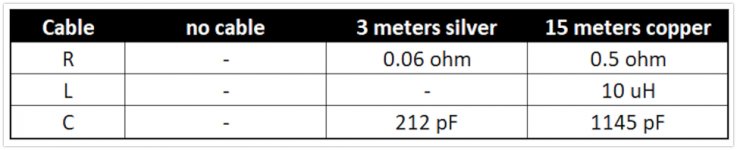
Because of the different RLC of the cables - the values are significantly different. Attached are the measured values (I have measured only the 3m and 15m cables) - they are pretty much in line with the model, described by Nelson Pass, for example.
Attachments
[OFF topic]
I got interested about the Ohm law bit.
Who is aware that it is not that easy to prove the Ohm law.
Because using a multimeter to measure the current througt a resistor and the voltage at its terminals is not a valid proof.
It is not valid because the multimeter is using the ohm law internally to display what is measured. This is something I remember from a physics teacher, I was one of his students, not asleep.
You need current measurement and voltage measurement that rely on other laws.
I got interested in, how to determine the unknown value of a resistor on a printed circuit. ( This was adressed to newbies. )
Sure you must lift one of the resistor terminals from the board. Then I simply use the multimeter in ohm mode to go at the resistor.
It must be amphasized that one of the resistor terminals MUST be lifted, otherwise the ohm measure is wrong.
Another recommandation is : Never do a ohm measurement on a live circuit. Always turn power off before going using the multimeter in ohm mode. Not only you'll likely get wrong measures, you have a chance to ruin the multimeter.
[/OFF topic]
[OFF topic]
I got interested about the Ohm law bit.
Who is aware that it is not that easy to prove the Ohm law.
Because using a multimeter to measure the current througt a resistor and the voltage at its terminals is not a valid proof.
It is not valid because the multimeter is using the ohm law internally to display what is measured. This is something I remember from a physics teacher, I was one of his students, not asleep.
You need current measurement and voltage measurement that rely on other laws.
I got interested in, how to determine the unknown value of a resistor on a printed circuit. ( This was adressed to newbies. )
Sure you must lift one of the resistor terminals from the board. Then I simply use the multimeter in ohm mode to go at the resistor.
It must be amphasized that one of the resistor terminals MUST be lifted, otherwise the ohm measure is wrong.
Another recommandation is : Never do a ohm measurement on a live circuit. Always turn power off before going using the multimeter in ohm mode. Not only you'll likely get wrong measures, you have a chance to ruin the multimeter.
[/OFF topic]
I addressed that saying you need a calibrated micro-ohm reader which is able to measure this without the inductance and without the probe wires and without the 10M resistor interacting on the readouts.
Such machines works and cost around 5K$. You cannot accurately measure a cable resistance with a voltmeter, seriously it will be wrong.
Why measure the resistance of a cable ? Just calculate it, from copper resistivity, lenght and diameter. Copper used in electric wires is of extremely pure copper with a well known resistivity. One can check the diameter of the wire with a caliper that costs about 50 bucks.I addressed that saying you need a calibrated micro-ohm reader which is able to measure this without the inductance and without the probe wires and without the 10M resistor interacting on the readouts.
Such machines works and cost around 5K$. You cannot accurately measure a cable resistance with a voltmeter, seriously it will be wrong.
R = r * L / S
S = Pi * D² / 4
Why measure the resistance of a cable ? Just calculate it, from copper resistivity, lenght and diameter. Copper used in electric wires is of extremely pure copper with a well known resistivity. One can check the diameter of the wire with a caliper that costs about 50 bucks.
R = r * L / S
S = Pi * D² / 4
this is very funny. Each wire length is different and varies greatly. When you measure 0.0X ohm each wire has different readings.
There can be discontinuities, micro-cracking, surface irregularities, core impurities which can be troublesome and unacceptable for 5000V at 60A three phase motors
") , I will keep saying it doesn't matter at all for audio if the wire is 0.01 or 0.02 ohm, only high frequencies will suffer at connectors or any soldering connection if there is a discontinuity.
, I will keep saying it doesn't matter at all for audio if the wire is 0.01 or 0.02 ohm, only high frequencies will suffer at connectors or any soldering connection if there is a discontinuity.Lets all pretend that's ok
Bueno, no fue tan bueno el ejemplo ( como me han observado ) que hubiera querido dar para demostrar que la NASA se esta perdiendo a un gran valor al no tenerme en cuenta....
[OFF topic]
I got interested in, how to determine the unknown value of a resistor on a printed circuit.
I got interested about the Ohm law bit.
Who is aware that it is not that easy to prove the Ohm law.
Because using a multimeter to measure the current througt a resistor and the voltage at its terminals is not a valid proof.
It is not valid because the multimeter is using the ohm law internally to display what is measured.
Yes, of course, if you take out the resistance totally and measure it, the matter is solved. It was by way of example, but you are right.
but, I do not see problems of physical laws here ....
If you need to adjust the rest current of the collector of a transistor, you will need to insert a milliammeter, ok? , but the more accuracy you require, the greater the impedance of the tester will have to be.
I do not think that more multimeters are made to valves, those were the best for these and many other tasks of precision .... In SS Hansen was approaching enough, now they talk to me about Fluke and I can not comment. I am already out of these leagues as a professional, I am just a simple spectator who watches the players from the rostrum, although wanting to replace the donkey that runs my favorite team ....
Last edited:
But why does wire length make a difference?
You must copy the name the link, use the search engine, download the pdf file and then open it.
Look here :
Page 14,15, and 16
[PDF]Amplifier Application Guide - HARMAN Professional Solutions
Last edited:
this is very funny. Each wire length is different and varies greatly. When you measure 0.0X ohm each wire has different readings.
There can be discontinuities, micro-cracking, surface irregularities, core impurities which can be troublesome and unacceptable for 5000V at 60A three phase motors
I really have not seen that level of variation. 60A is not so high. 5KV is also not a particular challenge. AC is distributed in local neighborhoods at 15KV and has for probably a century. Microcracking surface irregularities that are enough to degrade the DCR suggest processing problems. Either annealing or running the drawing process too fast. if you are seeing big differences (over 2% or so) change your cable supplier.
Typically a cable made of 16 AWG of any electrical grade copper comes out really close to the calculated number. Copper does have a significant temperature coefficient but not so bad as to invalidate measurements but big enough to swamp out the difference between TPC and 6N copper.
Yes, of course, if you take out the resistance totally and measure it, the matter is solved. It was by way of example, but you are right.
but, I do not see problems of physical laws here ....
If you need to adjust the rest current of the collector of a transistor, you will need to insert a milliammeter, ok? , but the more accuracy you require, the greater the impedance of the tester will have to be.
I do not think that more multimeters are made to valves, those were the best for these and many other tasks of precision .... In SS Hansen was approaching enough, now they talk to me about Fluke and I can not comment. I am already out of these leagues as a professional, I am just a simple spectator who watches the players from the rostrum, although wanting to replace the donkey that runs my favorite team ....
Valve multimeters need some significant voltage changes to work and they drift a lot. While there are interesting historical methods of measuring small currents (optical galvanometer Mirror galvanometer - Wikipedia) today there are many instruments that can measure small currents with a very small burden and high accuracy (QA150 High Side Current Sense Amp– QuantAsylum $139).
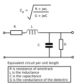
Certainly not a coincidence.Yes, there is nothing magic here. Make two cables where one has 10 times the capacitance and one tenth the inductance, I would expect the overshoot and phase properties to be different with the same load. Simply think of the damping factor of an RLC circuit it contains the same sqrt(L/C) as the RF impedance, not really a coincidence but RF vs audio does not figure into it.
When a cable L and C match an rf t line of the same impedance load, the total energy storage of the line is minimized. Also, the settling time of the system reduces to the propagation delay time of the cable.
When the cable's rf Z does not match the load's Z, settling time can be derived by either t-line or lumped L/R/C equivalently.
Doesn't everybody understand that when line Z equals load Z, the inductive storage equals capacitive storage, the total storage is minimum, and the delay is prop delay???
Scott, why bother?
Jn
Scott, why bother?
Jn
I did say not this again. I slipped it certainly is no coincidence, but I was hoping to make some peace over this. I could also point out that the exact equation for characteristic impedance has to be valid for R and G = 0 and gets us back to sqrt(L/C). Of course in the limit as f goes to 0 (DC) there is only energy stored in the capacitance. Too bad copper is not a super conductor
.
Last edited:
In the audio frequency range it is usually L which can be ignored. However, if sharp edges are being used then you need all three.scott wurcer said:Simply consider a lumped model of the line R, L, and C (R can probably be ignored) against a load resistor.
Only true for simple lines or approximate models. A transmission line can have a characteristic impedance which varies with distance (such lines are sometimes used for impedance matching) and it can change with frequency (e.g. a long line at audio frequencies).benb said:Here's an interesting article on characteristic impedance. One interesting property of a transmission line is the characteristic impedance is constant, and does not change with frequency.
No.j.michael droke said:Hi there a: If "frequency and geometry" (as mentioned above) are important to speaker cables, should we then use different cable geometry for low and high frequency cables for Biamped speakers?
Speaker cables are transmission lines, but they are so short at audio frequencies that it is entirely safe to use the low frequency approximation known as circuit theory i.e. treat them as lumped L C and R. In most cases within the audio range we can then ignore L and C.cbdb said:No. For the umpteenth time, speaker cables are not transmission lines.
Just in case this means there is no energy stored in an inductance at DC: This is wrong.Of course in the limit as f goes to 0 (DC) there is only energy stored in the capacitance.
Capacitors have E = 1/2 C*V²
Inductors have E = 1/2 L*I²
Forgive me, I do not understand speaker cables as transmission lines.
Last edited:
Just in case this means there is no energy stored in an inductance at DC: This is wrong.
Capacitors have E = 1/2 C*V²
Inductors have E = 1/2 L*I²
Forgive me, I do not understand speaker cables as transmission lines.
If the line is not terminated there is no DC I. The characteristic impedance formula is based on the unterminated case. I don't have access to an RF simulator that only uses the T-line formulation of cables, but I guarantee it does not throw an exception and will give exactly the same answer (hint: it has to).
Yes, why bother. I posted sims before but everyone seems trapped in knee jerk reactions to snake oil claims.
In most cases within the audio range we can then ignore L and C.
Tell that to the oscillating amplifier.
What formula ?The characteristic impedance formula is based on the unterminated case.
The characteristic impedance of a transmission line is what it says. It has nothing to do with how it is terminated, open or shorted or whatever terminating impedance.
What formula ?
The characteristic impedance of a transmission line is what it says. It has nothing to do with how it is terminated, open or shorted or whatever terminating impedance.
Characteristic impedance refers to the equivalent resistance of a transmission line if it were infinitely long, owing to distributed capacitance and inductance as the voltage and current “waves” propagate along its length.
Then, simplifying things, characteristic impedance Zo = SQR (L / C).
Now, in our case, the speaker cable is very short.
As soon as our speaker cable is unterminated (no speaker connected), we've got no current, so our L doesn't work (no energy stored in L).
Agree?
What formula ?
This one. The R serves to d-Q the inductance and the typical approximation of rising Z at low frequency is simply a manifestation of the dissipation in R overtaking the energy stored in L. Making R and G near 0 is fair, there is no law stating that the rise in Z can't be made to happen below audio frequencies. I don't like making these points because folks simply don't want to understand that both ways of looking at it give the SAME answer. I like to marvel at the internal consistency of the models and associated math YMMV.
Attachments
Last edited:
- Status
- This old topic is closed. If you want to reopen this topic, contact a moderator using the "Report Post" button.
- Home
- Amplifiers
- Solid State
- Speaker cables don't influence harmonic distortion!