Input with overdrive looks in LTSpice like that:
View attachment vorverstaerker_preamp_bluesman_2012_10_31.asc

It should be noted that
-Both Si-diodes are intended to prevent excessive differential input levels only, inhibiting any blocking distortion.
They do NOT contribute to distortion as diff pair distortion takes in at much lower levels.
-There is a significant bass cut before the overdrive and reciproke bass boost at the output. This improves response to chords.
-Overdrive is set by a tandem pot. The second section serves loudness correction.
-The range is from very close to clean upto heavy overdriven sound.
enjoy!
View attachment vorverstaerker_preamp_bluesman_2012_10_31.asc
It should be noted that
-Both Si-diodes are intended to prevent excessive differential input levels only, inhibiting any blocking distortion.
They do NOT contribute to distortion as diff pair distortion takes in at much lower levels.
-There is a significant bass cut before the overdrive and reciproke bass boost at the output. This improves response to chords.
-Overdrive is set by a tandem pot. The second section serves loudness correction.
-The range is from very close to clean upto heavy overdriven sound.
enjoy!
Last edited:
Learn from the mistakes of others too. Have a read ofFor now, at least, I want to investigate the JFET options before trying to make BJTs sound acceptable. I have been burned many times by nasty-sounding BJT guitar circuits, so I don't have a lot of faith that the differential amp overdrive idea will sound good to my ears.
Hamm, R. O. (1973). "Tubes Versus Transistors-is there an Audible Difference." Journal of the audio engineering society, 21(4), 267-273
which looks at spectra of various devices when overdriven.
It is included in a "Tube Primer and Selection" tutorial (from guitaramplifierblueprinting.com)
There's plenty more around: most of the technical content of this thread so far was covered by Cathode Ray's article in the Oct 1978 Wireless World. Which owes much to Crowhurst's article in the Oct 1957 JAES.
The Hamm paper was not particularly a good one, other papers by Monteith & Flowers or Mintz were more informative.
Thanks - do you have full references for the articles you refer to? I'd love to read them.
In any case, all of these papers are pretty dated, the devices and designs have since evolved.
How so? The physics hasn't changed

Mintz, R.S.: Comments on “Tubes Versus Transistors – Is there an Audible Difference?”, JAES (forum) Volume 21 p. 651; October 1973.
Monteith, D.O.; Flowers, R.R.: Transistors Can Sound Better Than Tubes, JAES Volume 25 Issue 3 pp. 116-119; March 1977.
Physics hasn't changed, but the SS manufacturing process have been improved quite a bit since the 1970's, not to mention there are far more component types available.
Monteith, D.O.; Flowers, R.R.: Transistors Can Sound Better Than Tubes, JAES Volume 25 Issue 3 pp. 116-119; March 1977.
Physics hasn't changed, but the SS manufacturing process have been improved quite a bit since the 1970's, not to mention there are far more component types available.
Thanks! There was also an IEEE spectrum article which looked at the curves in detail (somewhere around 1998) which concluded that some FETs looked almost like some valves, abeit with more noise at the same voltages.Mintz, R.S.: Commbents on “Tubes Versus Transistors – Is there an Audible Difference?”, JAES (forum) Volume 21 p. 651; October 1973.
Monteith, D.O.; Flowers, R.R.: Transistors Can Sound Better Than Tubes, JAES Volume 25 Issue 3 pp. 116-119; March 1977.
There is a superficial resemblance between FET curves and pentode / beam tetrode ones. I'm not sure how significant it actually is.some FETs looked almost like some valves, abeit with more noise at the same voltages.
What I think is significant, is that FETs (like valves, and unlike BJTs) have relatively low transconductance. They also have a relatively slow and smooth (square law) current-voltage characteristic, unlike the all-or-nothing exponential of a BJT.
All this means it's relatively easy to get some sort of smooth and progressive distortion out of a JFET or MOSFET. GJB seems to have taken this approach quite far, and was kind enough to share some of his circuit with us.
With BJTs, unlike FETs and valves, though, you usually go from sterile-clean to wasps-in-a-tin-can buzz with almost no transition in between. This is because BJTs have explosively high transconductance: where a 12AX7 has a datasheet transconductance of 1600 micro siemens at 1 mA anode current, a typical silicon BJT will have a transconductance of nearly 40,000 micro siemens at the same current!
The very high transconductance of BJTs usually leads to circuits with very high voltage gain. Too much gain, and too much ugly distortion - what to do? Engineers figured out the answer decades ago: you apply lots of negative feedback to control the excess gain, at the same time lowering all that nasty BJT distortion till its negligible. Great for Hi-Fi - but, as we've been discussing, utterly awful for guitar!
There may be an exception: Voltwide is using the one and only BJT circuit I know of which produces fairly smooth and progressive distortion. I haven't heard it in action, but I would guess that if any BJT circuit can sound good for distorted guitar, this one would probably be it!
Okay, that lone exception aside, JFETs are more likely to yield acceptable guitar sounds (than BJTs). The "Fetzer valve" approach is based on using a small, controlled, amount of negative feedback to make a JFET follow the Child-Langmuir law (which says that an ideal diode valve with parallel, infinitely large electrodes, has, under certain conditions, current flow proportional to the three-halve power of the anode voltage.)
Of course nobody amplifies a guitar with a vacuum diode, never mind one with infinitely large parallel plate electrodes. So all this might be more than a little academic. But we do have various good-sounding Runoff Groove pedals to show that the Fetzer Valve approach can make good sounds; we also have GJB's amp...
I haven't seen the paper in question, but this particular conclusion seems extremely questionable. The reason comes down to basic physics - a lot of the noise generated by an electronic device is driven by its absolute temperature (in Kelvin).FETs...like valves...abeit with more noise at the same voltages.
Room temperature is around 300 Kelvin. The kind of valves we use for our little audio circuits usually have the cathode at around 1300 Kelvin. Right there is a factor of four disadvantage for valves! Can you say "hissssss"?
")
The noise voltage (or noise current) from an ideal device is usually proportional to the square root of the temperature, but even so, BJTs and JFETs have a factor of two noise advantage over valves. (That's 6 dB improvement in shot noise.)
Along the same lines, you may know that when extremely good noise performance is required (for instance, NASA radio receivers receiving very weak signals from satellites), it's common to cool down the (solid state) electronics with liquid nitrogen. This drastically reduces thermal noise.
In practice, valves used for audio also suffer heavily from another type of noise called flicker noise. According to Merlin Blencowe (Valve Wizard), usually valve flicker noise is much bigger than valve thermal noise, so it actually dominates the overall noise performance.
And, guess what? JFETs not only have lower shot noise than valves, some JFETs have very low flicker noise, too! Some months ago I did some back-of-the-envelope calculations, and came to the conclusion that for low noise with guitar, JFETs are almost certainly the ideal device to use (i.e., better than valves, better than BJTs, better than MOSFETs.)
I still don't know whether we can make JFETs sound as good for guitar as real thermionic valves. But we can certainly make them quieter, if that's what we want!
-Gnobuddy
There is a superficial resemblance between FET curves and pentode / beam tetrode ones. I'm not sure how significant it actually is.
Joe Sousa and Ron Roscoe designed the Trioderizer specifically to emulate triode behaviour. The earliest source I've found is Joe's post on the Radiomuseum site in 2009.
There's a similar circuit known as a Fetzer Valve described by Tiago Charters de Azevedo who references Dimitri Danyuk, "Triode Emulator", 116th Audio Engineering Society Convention, May 2004 in Berlin, Germany (a paper I don't have)
Barbour, E., 1998. The Cool Sound of Tubes. IEEE Spectrum, 35(8), pp.24-35.I haven't seen the paper in question,
In particular the last paragraph of the distortion sidebar
ERIC BARBOUR said:Transistors operating on low-voltage supplies tend to have higher spectral distortion components than tubes.
If we go to high-voltage transistors, operating on supplies comparable to those of the tubes, the distortion products are less objectionable. Unfortunately, the noise floor of such devices is much higher. The IRF822 was very triode-like in distortion yet suffered from a noise floor some 30 dB higher than that of the triode.
No other active device possesses both the low distortion products and the low noise floor of the medium-mu triode--albeit at the expense of voltage gain.
I'm with you in thinking that JFETs are "the device most likely" for what you have planned.Some months ago I did some back-of-the-envelope calculations, and came to the conclusion that for low noise with guitar, JFETs are almost certainly the ideal device to use (i.e., better than valves, better than BJTs, better than MOSFETs.)
I still don't know whether we can make JFETs sound as good for guitar as real thermionic valves. But we can certainly make them quieter, if that's what we want!
Last edited:
Dimitri Danyuk, "Triode Emulator", 116th Audio Engineering Society Convention, May 2004 in Berlin, Germany (a paper I don't have)
Found it. http://www.diale.org/pdf/Triode-Emulator-by-Dimitri-Danyuk.pdf
You may consider these N-JFETs:
2SK3557 (OnSemi/Sanyo)
2SK392 (OnSemi/Sanyo)
2SK2394 (OnSemi/Sanyo)
BF862 (NXP)
LSK170 (Linear Systems)
All these outperform the "tradidional" BF245/BC264 and their derivates in terms of noise, transconductance and thighter gate voltage specs.
I consider these the ultimate guitar-pickup pre-amp devices.
Here is a thread on another forum where a BJT emulates a triode. Follow the link in the first post but you have to joint the forum to see attachments in the lower posts. The author has updated his website since he first posted.
https://www.ssguitar.com/index.php?topic=4114.0
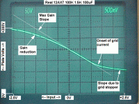
Below is an X-Y plot of a 12AX7 input vs output. You can see the non-linearity as the tube goes into cutoff. This is the characteristic that gives a tube preamp it's even order THD.
https://www.ssguitar.com/index.php?topic=4114.0
Below is an X-Y plot of a 12AX7 input vs output. You can see the non-linearity as the tube goes into cutoff. This is the characteristic that gives a tube preamp it's even order THD.
Attachments
I've read that web page a few times (I stumbled across it some years ago). One noteworthy aspect: the individual Id/Vgs curves of the Trioderizer do look a lot like a triode valves, but the Trioderizer curves are very uniformly spaced, unlike an actual triodes. That non-uniform spacing is what generates the lovely "tubey" or "valvey" distortion we like in guitar amps, so I have question marks in my head about how the Trioderizer would sound for guitar....designed the Trioderizer specifically to emulate triode behaviour.
I can post some graphs if this isn't making sense yet...
This has come up a number of times on this thread, and is the basis of GJBs preamp design.a Fetzer Valve...
I read it through, its aimed at Hi-Fi rather than guitar, and IMO has questionable value for our purposes.Barbour, E., 1998. The Cool Sound of Tubes. IEEE Spectrum, 35(8), pp.24-35.
The noisy "transistors" he talks about are high-voltage MOSFETs. These often suffer from high flicker noise, so they're probably not ideal guitar input stages. JFETs are a very different kettle of fish, though!
Mr. Barbour also comes to some other curious conclusions. He lists the difficulty of replacement as a disadvantage of transistors, for instance - but doesn't mention that transistors usually never fail in a good design, and don't usually need replacement for the life of the product! Contrast that with some famous guitar amps that "eat" output valves with alarming regularity.
Thanks for the endorsement!I'm with you in thinking that JFETs are "the device most likely" for what you have planned.
What I need to do is sit down at the workbench and actually build something. But this has been a rough month. One of those months where the universe has been poking me repeatedly with a sharp stick. No sooner has one crisis been partly staunched than another one erupts. The newest one erupted yesterday, this time involving the suddenly failing health of an elderly relative.
Let's hope things change for the better soon.
-Gnobuddy
Good design rarely makes it past the cost engineersb. And the life of the product is usually designed to be five minutes after the warranty expires.- but doesn't mention that transistors usually never fail in a good design, and don't usually need replacement for the life of the product!
Sadly all too true, these days. But I think some companies had very different attitudes in decades gone by, though. In 1990 I bought a can-opener that I used for the next twenty years. Solidly built, comfortable to use, robustly engineered. In 2015 I bought one that is mostly flimsy plastic, and it's already falling apart.Good design rarely makes it past the cost engineersb. And the life of the product is usually designed to be five minutes after the warranty expires.
But properly engineered solid-state electronics is incredibly reliable. There are no consumables (like coated cathodes and heated filaments) to wear out, after all.
I know that some low-power valve equipment has been known to work for decades with no valve replacements. At the same time, on a musician's forum, I've heard of a number of working musicians who gave up their valve guitar amps and replaced them with inferior-sounding solid-state ones, simply because they really needed better reliability.
If GJBs amp sounds even passably like a "real" AC-30, it could be a wonderful thing just from the reliability improvement aspect.
-Gnobuddy
Thanks for that! Very interesting to see it in this form, with input and output voltage plotted against each other. Exactly the transfer function that gives us the most information.Below is an X-Y plot of a 12AX7 input vs output.
That was taken with a triangle wave input, I take it, or some sort of similar linearly increasing ramp voltage?
-Gnobuddy
That was taken with a triangle wave input, I take it, or some sort of similar linearly increasing ramp voltage?
I usually use a sinewave and you have to adjust the frequency to get minimal looping. Most of the time it's between 200 and 500 Hz. I should mention that the circuit in the above post had a 33K grid stopper. The high frequency roll off causes a slight phase shift at the plate which causes the scope to display a loop.
Sometimes you can not close the loop. In posts 274 and 284 of this thread:
http://www.diyaudio.com/forums/pass-labs/215392-amp-camp-amp-aca.html
I posted an X-Y plot of one of Nelson Pass's power amps. His standard design shows a plot much like a triode but there is a loop caused by thermal distortion. The MOSFET is not the same temperature internally on the way up as it is on the way down. I showed how by selecting resistors the circuit could be linearized, but nobody seemed interested in lowering the distortion. After hours of listening to the ACA, I like the way it sounds even with the feedback disconnected. Nelson has another amp he calls the PLH were there is a pot that lets you adjust the amount of distortion. Link:
https://www.passdiy.com/project/amplifiers/the-plh-amplifier
Thank you for sharing the details. I really like the technique you're using to look directly at the voltage transfer function of a working amplifier (single stage or more).I usually use a sinewave and you have to adjust the frequency to get minimal looping. Most of the time it's between 200 and 500 Hz.
I have only once before encountered a similar set of plots, somewhere on the Internet, years ago. Those were obtained by driving a valve preamp (Fender, I think) with a trapezoidal signal - a triangle with the tops and bottoms cut off and replaced with flat plateaus. I don't remember the frequency range used, but it was within the normal range of guitar frequencies, and probably near the middle, just like the frequency you picked.
In effect, the amp was driven with a linear ramp with input and output voltages monitored, then given some time to settle down, before the signal repeated again. I think the scope was set to single-shot mode, but I'm not positive about that.
Well, in that particular case, I think you were dealing with a DIY subculture that has some of the characteristics of a cult. Cult members usually want to follow their leader. Suggestions that it may be possible to improve on the cult leader's work amount to heresy. Heresy doesn't fly well in a cult.I showed how by selecting resistors the circuit could be linearized, but nobody seemed interested in lowering the distortion.
I'm not interested in linear (Hi-Fi) solid-state power amps any more, though I was obsessed with them when I was young. They have been essentially perfect for decades now, and there are no interesting challenges remaining there.
But the sort of thing that this thread is about - deliberately non-linear analog solid-state amps that are designed to make a guitar sound good - is still interesting to me. I think it's an area that never fully matured in commercially available products, and the music electronics industry has moved on to digital hardware and software emulation of valve circuits.
That means there is still room for DIY hobbyists like us to make interesting little discoveries, and interesting little circuits. In other words, there's still some opportunity to have fun!
Perhaps it's time to bring up the fact that discrete, through-hole JFETs are now definitely an endangered species. Many old standby part numbers are already gone from the distributor websites, and those few still available are mostly designed for switching rather than analog amplification. Complete extinction of all discrete JFETs cannot be far away.
IMO, if we're going to be experimenting with JFETs, and need to actually buy new ones to use, the time window is small, and closing.
-Gnobuddy
As long as you don't clip them and give them "nice" loads. (There are exceptions but that's a whole 'nother threadI'm not interested in linear (Hi-Fi) solid-state power amps any more, though I was obsessed with them when I was young. They have been essentially perfect for decades now, and there are no interesting challenges remaining there.
)But the sort of thing that this thread is about - deliberately non-linear analog solid-state amps that are designed to make a guitar sound good - is still interesting to me.
Agreed on all points.
Perhaps it's time to bring up the fact that discrete, through-hole JFETs are now definitely an endangered species. Many old standby part numbers are already gone from the distributor websites, and those few still available are mostly designed for switching rather than analog amplification. Complete extinction of all discrete JFETs cannot be far away.
IMO, if we're going to be experimenting with JFETs, and need to actually buy new ones to use, the time window is small, and closing.
-Gnobuddy
That is another reason (besides the variability) that I prefer bipolar transistors. The exponential voltage control factor is absolutely predictable and seems equally capable of emulating triode curves. Even the noise performance can be pretty well the same at the sort of impedance levels seen in guitar pickups. There can be a bit more 1/f noise due to the base current, but this isn't particularly audible in practice and, once past the input stage, the designer is in control of the impedance levels.
My approach is to try to model the transfer function and the variation of harmonics with level :
http://www.aquinaudio.co.uk/valve_em.html
http://www.aquinaudio.co.uk/valve_em_further.html
Arthur
Very true!The exponential voltage control factor is absolutely predictable
And this is the part most of us haven't had much luck with!and seems equally capable of emulating triode curves.
I have two questions about your approach that I'm hoping you can answer:
1) Why use negative feedback? I'm familiar with the Taylor Series expansion of the exponential function, and its consequences for BJT distortion, which you discuss in your first white-paper. But I don't quite understand the reasons for adding negative feedback (which, as we've been discussing on this thread, usually modifies the nonlinear transfer function in an undesirable way for progressive guitar distortion).
2) The last figure in your second white-paper shows the amount of second harmonic distortion falling for input signals larger than 600 mV. This result is not predicted by the Taylor series expansion of an exponential function, and isn't seen in the corresponding distortion graph in your first white-paper.
I don't understand the reason for this fall in H2. Can you perhaps explain it?
-Gnobuddy
- Status
- This old topic is closed. If you want to reopen this topic, contact a moderator using the "Report Post" button.
- Home
- Live Sound
- Instruments and Amps
- Solid State version of a VOX AC-30 Guitar Amp