Susan Parker's Zeus (75W) has an output impedance of c. 2.78 Ω @ 1 kHz. This is based on 240 turns per side (actually split up into four sets per side) with the MOSFETs setup as "gate followers".
It does use a ton of iron - it'd be interesting to compare to a 75W amp based on PP 807s
It does use a ton of iron - it'd be interesting to compare to a 75W amp based on PP 807s
Yes, thanks, I was aware of all those issues.1) While connecting low impedance speakers may provide solve the problem from a different direction they may be difficult to obtain and/or configure.
2) Don't forget that the impedance ratio will be the SQUARE of the turns ratio. i.e. a 4:1 turns ration will produce a 16:1 impedance ratio.
3) 70 and 100 volt transformers will inherently have higher (rather than lower) ratios. 25 volt transformers will be better.
4) Low powered (10 watt) line transformers will also inherently suffer the same problem. A 25 watt unit was the lowest suitable I could find. (Details available if required)
")
If you look at my spreadsheet, you can see, for example, the impedances calculated using the square of the turns ratio. Also, it's no accident that one of the transformers I suggested is a 25V line transformer, and the other one a 100W transformer.
-Gnobuddy
With OTs generally size does matter.It does use a ton of iron - it'd be to compare to a 75W amp based on PP 807s
Sent from my LG-D801 using Tapatalk
I tried the simplest experiment of all - I switched an 8.2 ohm power resistor in and out of one speaker lead....it is my view that the reduced damping effect has a significant effect on the sound of the amp.
Adding an 8 ohm resistor reduces the damping factor to unity, and causes a 6 dB drop in power delivered to the speaker. The associated volume drop is audible, but rather slight. I was unscientific, and just tweaked the volume knob up a tad every time I flipped the switch that put the resistor in circuit.
Honestly, I heard little change in the sound of the amp. There were a couple of low notes (around the open "A" on the 5th string) that got a bit "woofier", but the effect was minor.
I was using an open-back cab with a 10" speaker (using my Princeton Reverb as a speaker cab). Bass is never very strong with a small open-back Fender cab, anyway, so that may have contributed to the fact that I didn't hear a whole lot of change in the sound.
But please don't take my word for it, try it yourself! Power resistors are cheap, and the experiment is simplicity itself. Ideally, get a friend to flip the switch back and forth while you play guitar - or get him/her to play guitar while you flip the switch back and forth.
It wouldn't be hard to add a 2:1 voltage divider at the input of the guitar amp as well, and using a DPDT switch, so that flipping the switch would raise the input voltage to the amp by 6 dB at the same time it inserted the speaker resistor and dropped the speaker output by 6 dB. Net result, no change in loudness, only a change in damping factor.
I should also mention that I was using clean tones only, and not playing very loud (I was in my living room). Perhaps things sound different with lots of distortion and lots of volume.
I would actually love it of some of you tried the experiment yourself. Perhaps some of you will hear something I didn't; perhaps you'll all hear the same thing I did. Either way, we'll learn something useful!
This is certainly true at frequencies around the fundamental speaker resonance, which is usually around 100 Hz for a guitar speaker.It effectively becomes much "looser" (for want of a better expression) and allows the speakers to move more freely.
Once we get high enough frequency for the cone to start flapping around (i.e. it's no longer rigid), the additional damping has very little effect. You can damp the voice coil motion, but the cone continues to "flap in the wind", not caring too much about what's happening back at the voice coil!
Most guitar speakers have large, thin, floppy cones, so I don't think we have to get very high in frequency before source impedance stops having much effect on the sound. I would guess that with the typical 12" guitar speaker, additional damping doesn't have much effect on the cone motion above 500 Hz.
Some guitar speakers have a distinctive tone because they are awful speakers! (But we love them for it.)Maybe this is why some guitar speakers (e.g. Celestions) have a distinctive tone?
If you don't mind, I'll climb up on my soapbox for a couple of minutes, and deliver a brief history lesson:
In the early days of the moving coil speaker, audio power was limited and very expensive. Speaker efficiency was all-important. The recipe was to use a very thin, light cone. It would be acceptably loud even with very few watts of power driving it.
Unfortunately, the thin, light cone wasn't rigid at all. Cone "break up" would occur at all but very low frequencies. Bits of the cone would flap wildly about, quite unrelated to the audio signal going into the voice coil. Horrible for accurate audio reproduction!
But, it turned out, all that wild, unruly, uncontrolled cone motion was actually pretty good for electric guitar. The guitar itself has a thin and uninspiring tone; all that crazy speaker distortion and "cone cry" made the guitar sound less boring and more interesting. Bad speakers are good for electric guitar!
Guitar speakers have more or less stayed stuck at that point in engineering evolution. They are, at first by accident, but nowadays by intention, bad speakers! Horribly peaky frequency response is normal. Huge amounts of distortion is normal. Crappy bass response (nothing below 100 Hz) is normal. Terrible dispersion (treble beams like a lighthouse) is normal. Huge amounts of "cone cry" is normal. Et cetera.
The world of Hi-Fi speakers moved on, though. Speaker engineers formed rings into the paper cone. As the audio frequency went up, the idea was that the outer rings of the cone would progressively stop moving (and making nasty noises), but the inner rings would continue to work, until eventually only the very centre of the cone was actually moving.
This worked to improve the sound a little, but only a little. You can find these rings in a few guitar speakers, too.
The next improvement was that the engineers came up with the "whizzer cone", a separate small stiff cone glued to the voice coil. The hope was that at high frequencies the big floppy cone would do nothing, and the stiff little whizzer cone would take over and produce accurate treble. They called these newly designed speakers "full range".
Those full-range speakers were a bit better yet. Some people still love them today. But they still have huge peaks and dips in the frequency response, they still have lousy treble dispersion, et cetera.
I have never seen one of these dual-cone, full-range speakers in a commercial guitar amp. Too new-fangled: this design advancement probably happened in the 1960s, and we all know guitar amp design is still stuck in the 1950s.
I've experimented with a couple of these dual-cone, full-range speakers in my own guitar amps. One of them produced lovely, vocal-sounding mids and trebles, but very weak bass. The other was better in the bass, but unremarkable in the treble. I really should try putting them both in one cab.
Back to the Hi-Fi speaker evolution story: the new-and-improved dual-cone, full-range, speakers were still very flawed. So speaker designers went on to design separate woofers and tweeters.
Woofers were big and stiff and heavy and designed to accurately reproduce bass. Tweeters were small and light and precise, to work well at treble frequencies. Efficiency fell off a cliff, but amps were getting powerful, and once semiconductors got good enough, watts soared, and costs plummeted. Efficiency hardly mattered any more. Accuracy was much better, and that's what was needed for Hi-Fi.
That's where the speaker design road ended, more or less, for Hi-Fi. Individual drivers got better, but no new revolutions came along.
Guitar speakers, though, have stayed stuck in the dinosaur era of speaker design, somewhere around the WW II era. They are bad speakers - very bad speakers - but we love the way they make our guitars sound!
And the opposite is true as well: if you've ever hooked up your solid-body electric guitar through a good Hi-Fi amp and speakers, you know how utterly horrible it sounds. Yikes!
-Gnobuddy
Speakers
Thanks Gnobuddy the history lesson was informative... seriously!
I particularly noted your comment about bad speakers being good for guitars... perhaps the same is true of amplifiers... they just need to be bad in a good way!
In lots of ways we are are now trying to put back what Engineers have been designing out over the last 50 or 60 years.
I've heard from a number of sources that smaller is better (to a point, you don't want them to actually overheat and fail) for guitar amps. The opposite for Hi-Fi, of course.With OTs generally size does matter.
I've never done my own experiments to verify this myself, though.
-Gnobuddy
I had a little time today, so I put together a little LTSpice sim to show what increasing amounts of negative feedback do, when applied around an amplifier with some gentle, progressive non-linearity in the transfer function.
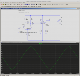
First up: a differential BJT pair, fed a rather small input signal, and no negative feedback (look at the feedback resistor value if in doubt).
Input signal is a triangle (best for viewing nonlinearity). Output signal is also a pretty good triangle.
-Gnobuddy
First up: a differential BJT pair, fed a rather small input signal, and no negative feedback (look at the feedback resistor value if in doubt).
Input signal is a triangle (best for viewing nonlinearity). Output signal is also a pretty good triangle.
-Gnobuddy
Attachments
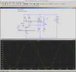
Here's what happens if you take the previous circuit, and drive it a bit harder. Input is still a triangle, not a sine. There is gentle, progressive distortion in the output - it looks more like a sinewave than a triangle due to this distortion.
(Note that there is still no negative feedback.)
-Gnobuddy
(Note that there is still no negative feedback.)
-Gnobuddy
Attachments
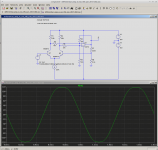
Here's what happens if we now apply just a tiny bit (6 dB) of negative feedback (that means the open-loop voltage gain has been halved due to the feedback.)
Look at the output waveform - it's quite straight in the middle, more like the triangle it's supposed to be. But when the output starts to clip, the clipping is more abrupt, and less progressive, than before.
That's what negative feedback does - it tries to make the amp linear, but that only works as long as there is excess voltage gain to trade for increased linearity. When the output starts to clip, there isn't any more excess gain, the feedback loses its grip on the situation, and abrupt overload happens.
-Gnobuddy
Attachments
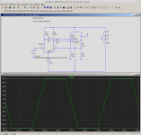
And now lets crank up the negative feedback - we're going to drop the gain from 200 (without feedback) all the way down to about 10 (with feedback). That's about 26 dB of feedback, more than most valve designs, but much less than most solid-state amps (including opamps).
We now have excellent linearity in the middle of the waveform, but harsh and abrupt clipping at the ends. Keep it from clipping (Hi-Fi) and it's great. But let it clip (guitar), and it's awful!
So, for use with guitar, I think GJB is absolutely on the right track when it comes to staying away from negative feedback.
(Negative feedback is a wonderful thing for Hi-Fi, and any other situation where you need an accurate amplifier.)
-Gnobuddy
Attachments
Your observations and conclusions are absolutely correct.
Negative feedback also affects residual noise, this should be considered as well.
I use the differential pair w/o neg feedback in the overdrive section.
Another differential pair with some feedback work as soft limiter between pre-amp and class-D power stage.
Negative feedback also affects residual noise, this should be considered as well.
I use the differential pair w/o neg feedback in the overdrive section.
Another differential pair with some feedback work as soft limiter between pre-amp and class-D power stage.
Totally agree with the comments about NFB not being a great idea in this application. And if the aim here still is to recreate some of the vibe of an AC30, let's keep in mind that the lack of NFB is considered by many to be a key part of the AC30's dynamic feel and touch sensitivity.
Sent from my LG-D801 using Tapatalk
Sent from my LG-D801 using Tapatalk
Thanks!Your observations and conclusions are absolutely correct.
I think negative feedback has a lot to do with many of the problems associated with solid-state guitar amps, and I think this is the first Internet thread I've seen where this issue has been recognized by multiple people. Yay for us!
The textbook version is that, when negative feedback is applied, output signal voltage and output noise voltage are both reduced by the same (feedback) factor. That leaves the signal to noise ratio unchanged.Negative feedback also affects residual noise, this should be considered as well.
Interesting, I don't think I've seen anyone do that before.I use the differential pair w/o neg feedback in the overdrive section.
Though, as you can see from the screenshots I posted, I had the same idea, probably for the same reason as you: I knew the transfer function of a differential amp is a smooth tanh() function, which is about the softest and gentlest limiting you'll ever get out of BJTs!
Now, that is an excellent idea!Another differential pair with some feedback work as soft limiter between pre-amp and class-D power stage.

I have a MOSFET "sourceodyne" phase splitter in my little valve guitar amp, where you'd normally find a cathodyne. I've used a similar concept there: the "sourceodyne" is preceded by a small-signal valve, and there is a fixed voltage divider in between the two. The valve stage can be overdriven, but the signal and power supply levels are chosen so that the MOSFET stage cannot: it remains in linear operation even if you massively overdrive the preceding valve.
In other words, nasty-sounding solid-state clipping can never occur. The "sourceodyne" is completely transparent as far as sound goes.
-Gnobuddy
Thanks!
The textbook version is that, when negative feedback is applied, output signal voltage and output noise voltage are both reduced by the same (feedback) factor. That leaves the signal to noise ratio unchanged.
-Gnobuddy
That is what I meant.
I discovered the smooth transition of BJTs in a RCA-Databook describing CA3080 transfer characteristic and immediately it was evident this was a nice approach for some guitar overdrive stage. By nature this produces odd harmonics. Adding some output signal to the current control input IABS gives asymmetric distortion as well.
I tested this and was not impressed, so I do not go for the even harmonics since then.
All in all the differential pair is just the modern incarnation of CA3080 OTA distortion being obsolete now.
I can provide some NOS CA3080 if there is any interest.
I think Sheryl Crow wrote a song about that exact concept (My Favourite Mistake)they (amplifiers) just need to be bad in a good way!
:https://www.youtube.com/watch?v=H59RbGzho9w
I agree, with the caveat that they were doing the right thing, if the goal was to accurately reproduce music.In lots of ways we are are now trying to put back what Engineers have been designing out over the last 50 or 60 years.
I think it took a long, long time before some people began to wake up to the idea that an imperfect amp was actually much better when it came to producing musical sounds with an electric guitar. Most electronics-savvy people I meet are still unfamiliar with the concept.
I myself learned this lesson the hard way: I grew up building solid-state, Hi-Fi (or at least Mid-Fi) amps. All I knew of valves was that they were inferior, and therefore already obsolete. So, when I took up electric guitar in my twenties, I built my own solid state guitar amps. And they all sounded horrible...design after design, year after year, until I eventually gave up.
Then I bought solid-stage guitar amps. They all sounded horrible too. Design after design, year after year.
It was a total revelation when I finally heard a hybrid (valve power amp, solid-state / DSP preamp) guitar amp. My guitars had never actually sounded good until then.
Things have moved on since then. Now we have some solid-state guitar amps that don't sound utterly horrible. I'm hoping to build one myself.
-Gnobuddy
Nice!I discovered the smooth transition of BJTs in a RCA-Databook describing CA3080 transfer characteristic
I first found a full theoretical analysis of the BJT differential amplifier transfer function in the book "Advanced Electronic Circuits" by Tietze and Schenk. The exponential transfer functions of the two BJTs combine to create a hyperbolic tangent (tanh) transfer function.
I first read this book in the late 1980s, and at the time, I never made any connection to the possibility of using it in a guitar amp. You were much smarter than me!
My experience is that a little bit (up to 20% - 30%) of mostly low-order even harmonics gives a nice "shimmer" to guitar clean tones. Very nice-sounding, but nothing like rock guitar - people don't hear it as distortion, just as a lovely clean tone. There is no "bite" or "growl" to the sound. Definitely not "rawk", more like early Mark Knopfler in Dire Straits.I tested this and was not impressed, so I do not go for the even harmonics since then.
For "rawk" music, I came to the same conclusion as you, that a mostly anti-symmetric transfer function (which generates mostly odd harmonics) was the way to go.
In the valve world, beam tetrodes generate a lot of second harmonic (this was considered a weakness, as described in the original white paper on the design of the 6L6). True pentodes tend to generate less second harmonic, but lots of third harmonic.
Probably not a coincidence that many people like SE 6V6 amps for cleans (lotsa 2nd harmonic). And many people like SE El84 amps for rock (lotsa 3rd harmonic).
-Gnobuddy
Some of the old function generator chips used a diff pair to convert a triangle wave to sine wave. Can you make a soft clipping circuit by using emitter degeneration in a diff pair?
I strongly agree that circuits without AC feedback sound a whole lot better for guitar. For a preamp stage you want THD to slowly rise with signal level and hit about 10% before actual clipping.
I strongly agree that circuits without AC feedback sound a whole lot better for guitar. For a preamp stage you want THD to slowly rise with signal level and hit about 10% before actual clipping.
Yes indeed! A few months ago I decided to build a function generator to test my guitar circuits with, and I began to look around for ideas. I found an app note that listed a number of ways to generate sine waves, including the method you mentioned: using a differential amp stage to "round off" the triangle. I'd seen that clever trick decades ago, but forgotten about it.Some of the old function generator chips used a diff pair to convert a triangle wave to sine wave.
But when I was reminded of the idea recently, that's when it occurred to me that it might be worth a try in a guitar overdrive circuit. But evidently Voltwide got there long before I did.
There is a catch, to the "differential amp overdrive" idea though: the amount of input voltage at which overdrive begins is completely out of our control, fixed by the properties of silicon transistors, and room temperature. And it only takes quite a small signal voltage for overdrive to occur.
To be specific, there is almost linear operation at 50 mV peak to peak input signal, and quite a lot of distortion at 250 mV peak to peak. Just beyond 250 mV comes full-on clipping.
These are quite small voltages, so I think you won't need much gain between guitar and diff. amp stage. Voltwide could probably tell us more, as he's got a working circuit he designed.
Emitter degeneration is a form of negative feedback. Like all forms of negative feedback, it will have exactly the wrong effect for our purposes: it will make the circuit more linear for small signals, but it will also cause a more abrupt onset of overdrive. Just like the LTSpice screenshots I posted.Can you make a soft clipping circuit by using emitter degeneration in a diff pair?
In other words, emitter degeneration resistors will try to create the usual solid-state guitar amp problem: it sounds too clean when clean, and too harsh when overdriven.
The catch is that if we don't use any emitter resistors, we will probably end up with one transistor turned off, and the other one hogging all the current, because our two transistors won't be identical. That won't work as a differential amp!
I think I have a solution, though: DC bias each transistor individually, then couple the emitters together with a big cap. It'll act like a diff. amp as far as AC signals are concerned, but like two independent transistor stages when it comes to DC biasing.
For now, at least, I want to investigate the JFET options before trying to make BJTs sound acceptable. I have been burned many times by nasty-sounding BJT guitar circuits, so I don't have a lot of faith that the differential amp overdrive idea will sound good to my ears.
I could be wrong, of course!
-Gnobuddy
Emitter degeneration is a form of negative feedback. Like all forms of negative feedback, it will have exactly the wrong effect for our purposes: it will make the circuit more linear for small signals, but it will also cause a more abrupt onset of overdrive. Just like the LTSpice screenshots I posted.
In other words, emitter degeneration resistors will try to create the usual solid-state guitar amp problem: it sounds too clean when clean, and too harsh when overdriven.
-Gnobuddy
This is certainly true. If you feed the differential pair by a current source, there is an asymptotic output limit given by 0/100% collector current. This I consider a nice effect, i.e. loudness does not increase on heavy overdrive - other than any diode limiters.
Degeneration emitter resistors give us the choice for more or less linearization. I use them in the soft limiter section between pre-amp and power stage to reduce master gain a bit.
- Status
- This old topic is closed. If you want to reopen this topic, contact a moderator using the "Report Post" button.
- Home
- Live Sound
- Instruments and Amps
- Solid State version of a VOX AC-30 Guitar Amp