Hi Gnobuddy. As I noted I have not provided any direct description of my circuit but if there are parts that you require some explanation please let me know and i will do my best.
Also... I have designed a complete PCB for this... which potentially I could make available... maybe even supply the 2SK series FETs I have used?
... and being a "newby" here I'm wondering if it something that the DIYAudio store might be interested in???
I might put up a few pics on the main page.
GJB
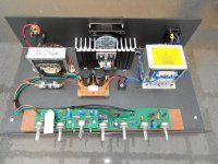
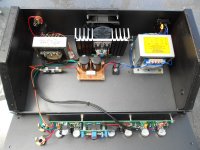
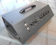
Solid State AC-30 Amp - a few pics
Hi people. A few pics of the above attached (with the "hood off" FYI.
Please note the block of wood was purely for "Insulation purposes" while I did my testing!")
Hi people. A few pics of the above attached (with the "hood off" FYI.
Please note the block of wood was purely for "Insulation purposes" while I did my testing!
Attachments
Ouput Transformers
Hi Zen... good question! In fact I am sort of surprised that nobody has asked about transformers previously as this is a CRITICAL part of the design and goes a long way to providing the "valve amp" sound... because that's EXACTLY what valve amps use. Sort of obvious when you think about it!
Anyways... initially I simply used a 1+1:1 transformer. I sort of worked backwards and set up my supply voltage and MOSFET currents to match. Problem was that the Trani needed to be custom wound and was relatively expensive. I could not find an off-the-shelf product... and/or at a realistic price.
Nowadays I have found an off-the-shelf 25 volt line transformer which has the correct taps to make a 1.4+1.4:1 device. As above I modified my supply voltage and FET currents to provide the correct match. The trani is nominally 25 watts... but stretches to 30 (to give the same power output as the AC-30) without any problems... in fact a bit of transformer saturation can be desirable.
The original (1+1:1) trani which was (over-designed) for 100 watts I have now used in a 150 watt version of the AC-30... what a beast!
When connected to a Celestion Quad-box it (literally) shakes the windows!
Transformer - PS
Ooops... The transformer is a 50 volt line transformer... not 25 volts... I was thinking watts!
50 volt line transformers are not common. Generally they are (at least) 70 volt units - and more commonly 100 volts.
There is a good article about how this works at
Cheap Output Transformers
It is written in the context of valve amplifiers... but exactly the same principles apply.
GJB
Hello to all,
sorry if I intrude, but I wanted to ask your advice because I have a problem with my VOX AC30SS ..
I have a cable connection problem of VIBRATO tab, I do not understand how to connect and restore the transformer wires ..
You can help you understand how to connect them?
I hope he was not too pushy, eventually, I apologize and I open new thread.
photo:
Thank you in advance for your response and the help
sorry if I intrude, but I wanted to ask your advice because I have a problem with my VOX AC30SS ..
I have a cable connection problem of VIBRATO tab, I do not understand how to connect and restore the transformer wires ..
You can help you understand how to connect them?
I hope he was not too pushy, eventually, I apologize and I open new thread.
photo:
An externally hosted image should be here but it was not working when we last tested it.
An externally hosted image should be here but it was not working when we last tested it.
An externally hosted image should be here but it was not working when we last tested it.
An externally hosted image should be here but it was not working when we last tested it.
An externally hosted image should be here but it was not working when we last tested it.
Thank you in advance for your response and the help
Hello to all,
sorry if I intrude, but I wanted to ask your advice because I have a problem with my VOX AC30SS ..
I have a cable connection problem of VIBRATO tab, I do not understand how to connect and restore the transformer wires ..
You can help you understand how to connect them?
I hope he was not too pushy, eventually, I apologize and I open new thread.
photo:
Thank you in advance for your response and the help.
sorry if I intrude, but I wanted to ask your advice because I have a problem with my VOX AC30SS ..
I have a cable connection problem of VIBRATO tab, I do not understand how to connect and restore the transformer wires ..
You can help you understand how to connect them?
I hope he was not too pushy, eventually, I apologize and I open new thread.
photo:
An externally hosted image should be here but it was not working when we last tested it.
An externally hosted image should be here but it was not working when we last tested it.
An externally hosted image should be here but it was not working when we last tested it.
An externally hosted image should be here but it was not working when we last tested it.
Thank you in advance for your response and the help.
Can you kindly tell us more about what differences in sound you heard, when switching from a transformerless to transformer-coupled output stage?...this is a CRITICAL part of the design and goes a long way to providing the "valve amp" sound...
I know that transformers can produce enough distortion and bass loss to be audible, but I've never done a back-to-back comparison, so I'd love to hear more about your findings.
I've found some low-power audio line transformers that have both "70V" and "25V" primaries. The ones I found are only rated for 10 watts, but that might be plenty for my project. Ten watts is more than loud enough for the friend I want to build the amp for.
-Gnobuddy
Hi casarete, may I suggest you open another thread?Thank you in advance for your response and the help
I think you will get more responses and help if you start your own thread with a proper title, maybe "Vox AC 30SS Vibrato problem" or something like that.
Also, I was unable to view your photos. Perhaps you can check the viewing permissions of your Flickr folder, or attach the images directly to your new thread (rather than linking to an online Flickr folder).
Good luck!
-Gnobuddy
I'm fairly new here myself. Dunno how you'd go about this, but perhaps send a private message to a moderator and ask?... and being a "newby" here I'm wondering if it something that the DIYAudio store might be interested in???
-Gnobuddy
I think you will get more responses and help if you start your own thread with a proper title, maybe "Vox AC 30SS Vibrato problem" or something like that.
Good luck!
-Gnobuddy
thanks a lot Gnobuddy,
I follow your advice and I open a new thread ..
More on Audio Transformers
Hi people... to address Gnobuddy's queries:-
Firstly I haven't "swapped" the output stage of my amp between direct and transformer as such so can't compare in that way.
Direct coupling will, in some respects, sound like playing through a hi-fi amp... notwithstanding whatever the preamp adds.
Transformers do a number of things... which are mentioned on my initial post on this thread. Suffice to say the sound texture is changed considerably. While I will leave you to google the details transformers do not have a linear transfer characteristic. It is something of an "S" shape... particularly where it gets near saturation. This is CRITICAL! It means no harsh clipping... more of a rounding of the signal.
Also transformers become less efficent at lower (bass) frequencies. Their power handling capability is thus determined at the low end. Again Lots on google about this.
As for the (10 watt) transformers you have found... be careful. Working out the correct impedance taps is tricky. Although it is in the context of valve amps the link Cheap Output Transformers explains this.
Of course you also need to match the impedance of the MOSFET drivers to the transformer as well. Setting up supply voltages and currents is important. There is a bit of "Electronics 101" (and maybe 102 & 103) involved here.
Preamp
Just a bit more on my preamp comment.
Solid State Guitar Amps almost invariably try to get the "sound" they want by doing all sorts of tricks and processing in the preamp. Sometimes it works... many times it doesn't! :-(
Some stomp boxes work the same way. All the processing is done in the box... and then simply fed to a "regular" amp.
My amp is (very) conventional in design. There is no deliberate or calculated components to "add" to the sound.
Its characteristics are simply what they are by going back to the "roots" of how it got there in the first place.
[PS - Gnobuddy are you able to send me the model # and/or the spec of the transformer you are considering?]
I actually think we're not too far apart, and I have no doubt at all that biasing can play a helpful role. From what I can see most modern semiconductor amplification devices will hard-clip when they swing to either rail. In other words, they're good at generating square waves. Their characteristic curves also tend to be very straight sided with an angular knee. And these are what op amps are basically made from. Sure, they have a ridiculous amount of open loop gain, reduced down to useful levels by the use of a lot of NFB, but ultimately, opamp's clipping characteristics reflect the devices they're made from.Hi Aqua... I beg to differ... sorry
The distortion characteristics are different... and it not only depends on what type of device - but also how it is biassed. "straight edged and harsh!/fizzy sounding" (as you have termed it) tends to happen mainly where opamps are used and the large amounts of negative feedback drive the device to (or near) the supply rails from which they simply can not go any further.
So we may try to improve the situation through biasing, but what are we actually doing here? We could possibly improve the distortion tone by biasing a FET preamp stage asymetrically, so that one side clips more than the other, tso it produces more even order harmonics. A similar effect could also be achieved by having different diodes wired antiparallel, which is what I did in my unexpectedly successful Boss DS-1 modding experiment.
Ultimately, all of these approaches will still yield a square wave when pushed to extreme amplitude, whereas a common-cathode valve preamp stage will remain stubbornly asymmetrical, with the lowest excursions never managing to hit the 0V rail, and with rounded shoulders on the lower extremities. It should be possible to simulate this characteristic as well with some combination of semiconductor devices, but it will be starting to get complicated.
Yes, I got that.Also - and in respect of the Fetzer process - my understanding is that it is designed to bias the FET in that part of its transfer characteristic where it (best) approximates the "three-halves" valve characteristic.
However, I can't help being curious about what happens at extremities of the output waveform, when a Fetzer stage swings close to the rails. I wonder if there's some rounding off the clipped waveform due to the DC NFB, similar to what happens in the clipping stage of certain well known high-gain guitar amplifiers. If so, that might help explain why you find Runoffgroove's pedals sound better, and would provide a great example of how you can indeed bias to improve the sound of a FET preamp stage. I told you we weren't that far apart. Absolutely! It would be impossible for me to agree more. Nothing like an OT to add in some vintage-style warmth. Some of Vox's early transistor amplifiers also used this approach, and some even used an interstage transformer for the PI. By all accounts they sounded pretty decent!laying through a hi-fi amp... notwithstanding whatever the preamp adds.
Transformers do a number of things... which are mentioned on my initial post on this thread. Suffice to say the sound texture is changed considerably. While I will leave you to google the details transformers do not have a linear transfer characteristic. It is something of an "S" shape... particularly where it gets near saturation. This is CRITICAL! It means no harsh clipping... more of a rounding of the signal.
Also transformers become less efficent at lower (bass) frequencies. Their power handling capability is thus determined at the low end. Again Lots on google about this.
As for the (10 watt) transformers you have found... be careful. Working out the correct impedance taps is tricky. Although it is in the context of valve amps the link Cheap Output Transformers explains this.
Of course you also need to match the impedance of the MOSFET drivers to the transformer as well. Setting up supply voltages and currents is important. There is a bit of "Electronics 101" (and maybe 102 & 103) involved here.
Last edited:
Agreeing with most of what's above - it's all about behaviour at clipping. The architecture of OP-amps (which is the architecture of most solid state amplifiers and some valve amps) results in harsh clipping. And more often than not, that clipping upsets all sorts of internal circuitry, requiring a significant amount of time to recover.
There are various SS hi-fi amps which try to avoid this, including Susan Parkers's amp which uses the same principles as you espouse.
There are others which go further and deliberately select an asymmetric architecture (e.g. Ranchu32's amp).
As you note, runoffgrove has a number of FET based designs but they eventually went op-amp (carefully NOT clipping them) in their non plus ultra Thunderbird
For another example of controlled (soft) clipping you should have a look at the limiter stage of Fred Nachbour's Dogzilla
Another neat tweak he's done is to utilise a small amplifier, complete with transformer and speaker load within the preamp to get that "flat out" sound at lower volumes. He has left us a bit of cliffhanger as it appears he never published his ultimate solution.
Overdriving a standard "line" transformer (e.g. 10k:10k) is another popular way to get some compression/limiting without creating squarewaves. It's the reason input transformers are still found in most top-end mixing desks.
I found Roly Roper's website about using 100V line transformers in valve guitar amps years ago. I had no time or energy for electronics then, but I did put together a spreadsheet listing the locally available (USA) 70V audio line transformers that I thought might be useful for a someday valve guitar amp build.PS - Gnobuddy are you able to send me the model # and/or the spec of the transformer you are considering?
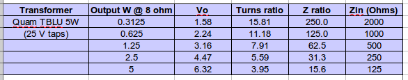
Using my spreadsheet, I found two locally available transformers that are in the ballpark for GJB's amp design. Screenshots of my spreadsheet entries for both are attached.
The first candidate is a 5W Quam unit (available at Parts Express, very inexpensive: Quam TBLU 5W-25/70V Speaker Line Matching Transformer Multi-Tap
On the 25V primary, there is a 5W tap, which corresponds to a 4:1 turns ratio. There is also a 1.25W tap, which is an 8:1 turns ratio.
So you can use this transformer with the 5W tap as the centre-tap, the "common" tap as one end, and the "1.25 W" tap as the other end. The turns ratio is 4:1 for each half, rather than the 1.4:1 you (GJB) specified.
Not ideal, but if you put a 1 ohm speaker on the secondary, you'd get exactly the same primary impedance GJB gets from his 1.4:1 transformers. More practically, two 4 ohm speakers in parallel will probably work just fine, with MOSFET supply voltage adjusted accordingly.
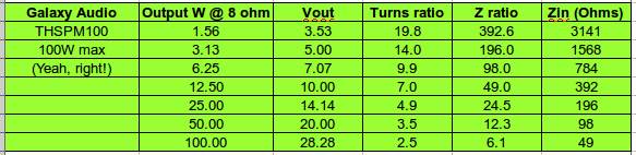
The second transformer that looks like a possibility, is a nominally 100 watt Galaxy audio unit. Not cheap:
Galaxy Audio THSPM100 70 / 100 Volt Audio Transformer
Higher powered audio line transformers have lower turns ratios, which is what we want in this particular case.
Look at my second attachment for the Galaxy transformer. Turns ratio is 2.5:1 for the 100 watt tap, and 5:1 for the 25 watt tap. So the 25 W tap is the centre-tap; use the 100W and "common" leads for the two MOSFET drains.
We need to roughly quarter the primary impedance, so using a 2 ohm speaker will do the trick; as before, two 4 ohm speakers in parallel is probably the way to go.
Mind you, it's quite possible that these will work just fine with 8 ohm speakers, with the power MOSFET supply voltage adjusted accordingly.
Personally, I'm not yet convinced that an output transformer is the only way to make a MOSFET output stage sound good with a guitar. But I might very well be wrong.
For those who want to try the transformer route, the QUAM unit in particular seems worth a try - it's very inexpensive, so well worth a try for a little 5W or less amp. (My 2W valve amp is way too loud at home, unless I dial down the output power with an L-pad.)
I have more to say, but I have responsibilities to take care of. I'll be back later.
-Gnobuddy
Attachments
Amplifier Impedances
To answer Loud Thud's question... the impedance looking back in to the amplifier is around 8 ohms... as it should be driving an 8 ohm load. It has beeen designed that way.
This provides a damping factor significantly lower than a standard (direct coupled) amplifier which are around 0.1 ohm or less... thus producing damping factors around 100 or more.
Again as per my initial post... it is my view that the reduced damping effect has a significant effect on the sound of the amp. It effectively becomes much "looser" (for want of a better expression) and allows the speakers to move more freely. Maybe this is why some guitar speakers (e.g. Celestions) have a distinctive tone?
Transformers
Hi Gnobuddy... While your theory sounds fine there may be some practical problems. For use in SS circuits transformers need (generally) to have as low turns ratio as possible... normally between 1:1 and 2:1 or thereabouts.
The problems you may have include:-
1) While connecting low impedance speakers may provide solve the problem from a different direction they may be difficult to obtain and/or configure.
2) Don't forget that the impedance ratio will be the SQUARE of the turns ratio. i.e. a 4:1 turns ration will produce a 16:1 impedance ratio.
3) 70 and 100 volt transformers will inherently have higher (rather than lower) ratios. 25 volt transformers will be better.
4) Low powered (10 watt) line transformers will also inherently suffer the same problem. A 25 watt unit was the lowest suitable I could find. (Details available if required)
Having said all of that... what you are suggesting is still possible... but you will need an output set up for higher voltage and lower current operation... to get your load line matching the transformer. Something like 2SK2013' s would be possible. I have some of these!
Cheers,
GJB
- Status
- This old topic is closed. If you want to reopen this topic, contact a moderator using the "Report Post" button.
- Home
- Live Sound
- Instruments and Amps
- Solid State version of a VOX AC-30 Guitar Amp