I like the slider instead of the wheel. Would probably be easier to use on something sitting on a shelf, plus it's less i-podish.
still, it requires the whole serial stream interpretation glob of components (more than I have time to deal with).
I was thinking of using frosted glass (etched on the inside) with leds mounted on the edge so the whole thing acts like a light pipe, and glows sort of indirectly.
Because I have a 2-year old, I was also thinking of adding an unlabled touch area in one of the corners which would toggle whether all the other areas are active (control lock). Just have to be crafty about using it so he doesn;t see me.
implementing into...
They offer an evaluation brd w/ schematic...
http://www.qprox.com/products/e11x.php
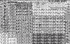
here is the schematic for the E11X...
but yes, I could not slip this in if it would work.
They offer an evaluation brd w/ schematic...
http://www.qprox.com/products/e11x.php
here is the schematic for the E11X...
but yes, I could not slip this in if it would work.
Attachments
Yeah, that's easy. The slider has a serial output, which means you need a microcontroller etc to interpret the signals and pass them to a digital volume control. The DS1802 has a simple VolUp/Down button interface, so you could use two 110s for that, and another in toggle mode for power. Maybe a source selector too, if you can find a selector IC you can live with, or maybe drive a lagic chip then an array of relays. I need to spend some time with this....
Merging soft power-up circuit with output protection. Comments?
Basic design:
Separate power supply for driver stage. Includes time delay to relay for soft turn-on of output power supply. The driver circuit includes a servo to control DC offset, and a shelf circuit which triggers if the output has significant DC from a short circuit or shorted output transistor.
Output power supply has soft turn-on resistor and shunt relay that shorts out this resistor after the timer on the driver board triggers and the shelf circuit is off. This relay is DPDT, and also has a 1 ohm resistor between the amp output terminal and ground in the "off" position.
Main power switch turns on driver supply and the soft turn-on resistor path to the output power supply. When the timer on the driver triggers AND the shelf circuit signals "no short", then the turn-on relay is activated and the 0.1 ohm shorting resistor removed from the output.
If an output short occurs, then the relay falls open, the 1 ohm shunt resistor in put in parallel with the speaker to protect it, and the output power supply is run on the limited current from the soft power-up resistor. If the short goes away, normal operation is returned.
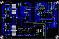
I had thought about this, but I was trying to keep the board as small as possible. This would certainly increase the size quite a bit. To help out a little, I added some testpads so that any other additional 'accessory' boards could use the power off this board. I also decided to put a decent line/DC filter on the front end. The board is still fairly small, coming in at approximately 5" x 3.25". Here's a screenshot...
Attachments
And here's the obligatory .brd file...
I based the line/DC filter on the one in this post. The addiotional cost is only about $15. I'll update the BOM and post that soon as well.
Just out of curiosity, would there be enough people interested in this to do a small board order?
I based the line/DC filter on the one in this post. The addiotional cost is only about $15. I'll update the BOM and post that soon as well.
Just out of curiosity, would there be enough people interested in this to do a small board order?
Attachments
ble0t said:
Just out of curiosity, would there be enough people interested in this to do a small board order?
Yes, at least two, maybe more.
Thank you Ble0t...
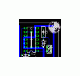
sklimek said:Hi, would this mounting hole taken from your latest version be a problem?
How so?
ble0t said:OK...gotcha...that's actually a 'fill' that is on the board (polygon tool). Hit the 'Ratsnest' button to have it fill in and also avoid the restricted area of the mounting hole.
O.K. - Dam* that board is pretty...
- Status
- This old topic is closed. If you want to reopen this topic, contact a moderator using the "Report Post" button.
- Home
- Amplifiers
- Solid State
- Soft start & Soft Switch circuit: can anybody help?


