IRFP240/IRFP9240 SlewMaster
I am intending to build as FET version of the SlewMaster when my boards arrive.
In the meanwhile I have created the list below of component needed.
I have these question:
Do I fit Q105 and Q106 and B links or just B links?
FET BOM
C101 - 20nF - 100V, Pin Spacing: 5.08mm
C102 - 22uF - RP 100V, Body Height - 12mm, Diameter – 8mm, Pin Spacing: 3.5mm
C103 - 220uF - RP 100V, Body Height - 27mm, Diameter – 16mm, Pin Spacing: 7.5mm
C104 - 20nF - 100V, Pin Spacing: 5.08mm
C105 - 22uF - RP 100V, Body Height - 12mm, Diameter – 8mm, Pin Spacing: 3.5mm
C106 - 220uF - RP 100V, Body Height - 27mm, Diameter – 16mm, Pin Spacing: 7.5mm
C107 - 1uF - RP 50V, Body Height - 10mm, Diameter – 5mm, Pin Spacing: 2mm
C108A - N.F. - 100V Pin Spacing: 5 or 7.5mm
C108B - 33pF - 100V, Pin Spacing: 5.08mm
C109A - N.F. - 100V, Pin Spacing: 5.08mm
C109B - 33pF - 100V, Pin Spacing: 5.08mm
C110 - 20nF - 100V, Pin Spacing: 5.08mm
C111 - 470uF - RP 100V, Body Height - 16mm, Diameter – 10mm, Pin Spacing: 5mm
C112 - 20nF - 100V, Pin Spacing: 5.08mm
C113 - 470uF - RP 100V, Body Height - 16mm, Diameter – 10mm, Pin Spacing: 5mm
C114 - N.F. - 100V Pin Spacing: 5 or 7.5mm
C115 - 100nF - 100V Pin Spacing: 5 or 7.5mm
C116 - 1000uF - RP 100V, Body Height - 40mm, Diameter – 22mm, Pin Spacing: 10mm
C117 - 100nF - 100V Pin Spacing: 5 or 7.5mm
C118 - 1000uF - RP 100V, Body Height - 40mm, Diameter – 22mm, Pin Spacing: 10mm
C119 - 100nF - 100V Pin Spacing: 5 or 7.5mm
Dled - - Blue LED
D101 - 1N914 - Small Signal Fast Switching Diodes
D102 - QTLP690C - Red LED
D103 - 1N914 - Small Signal Fast Switching Diodes
D104 - BZX84C12L - 225 mW 12 V ±5% Zener Diode Voltage Regulator
D105 - MURS120 - ULTRAFAST RECTIFIER, 1.0 AMP 200 VOLT
D106 - MURS120 - ULTRAFAST RECTIFIER, 1.0 AMP 200 VOLT
D107 - BZX84C12L - 225 mW 12 V ±5% Zener Diode Voltage Regulator
D108 - MUR460 - ULTRAFAST RECTIFIER, 4.0 AMP 600 VOLT
D109 - MUR460 - ULTRAFAST RECTIFIER, 4.0 AMP 600 VOLT
D110 - MUR460 - ULTRAFAST RECTIFIER, 4.0 AMP 600 VOLT
D111 - MUR460 - ULTRAFAST RECTIFIER, 4.0 AMP 600 VOLT
- -
L1 - 1.5uH - 18 turns of 1.25mm wire, 12mm Diameter
- -
Q101 - MJE340 - NPN Transistor 0.5 AMP 300 Volt
Q102 - MJE350 - PNP Transistor 0.5 AMP 300 Volt
Q103 - MJE340 - NPN Transistor 0.5 AMP 300 Volt
Q104 - MJE340 - NPN Transistor 0.5 AMP 300 Volt
Q105 - 2SC3503 - NPN Transistor 0.1 AMP 300 Volt
Q106 - 2SA1381 - PNP Transistor 0.1 AMP 300 Volt
Q107 - 2SC4793 -
Q108 - 2SA1837 -
Q109 - IRFP240 -
Q110 - IRFP240 -
Q111 - IRFP240 -
Q112 - IRFP240 -
Q113 - IRFP240 -
Q114 - IRFP9240 -
Q115 - IRFP9240 -
Q116 - IRFP9240 -
Q117 - IRFP9240 -
Q118 - IRFP9240 -
- -
Rled - 100k - 500mW
R101 - 470R - 500mW
R102 - 22k - 500mW
R103 - 1k8 - 500mW
R104 - 1k2 - 500mW
R105 - 1k2 - 500mW
R106 - 500R - Bourns 3296 – 10 turn potentiometer
R107 - 390R - 500mW
R108 - 22k - 500mW
R109 - 470R - 500mW
R110 - 1k - 500mW
R111 - Link
R112 - Link
R113 - 1K - 1W+
R114 - 10R - 1W+
R115 - 10R - 1W+
R116 - 270R - 500mW
R117 - 270R - 500mW
R118 - 270R - 500mW
R119 - 270R - 500mW
R120 - 270R - 500mW
R121 - 270R - 500mW
R122 - 270R - 500mW
R123 - 270R - 500mW
R124 - 270R - 500mW
R125 - 270R - 500mW
R126 - 0R22 - 5W
R127 - 0R22 - 5W
R128 - 0R22 - 5W
R129 - 0R22 - 5W
R130 - 0R22 - 5W
R131 - 0R22 - 5W
R132 - 0R22 - 5W
R133 - 0R22 - 5W
R134 - 0R22 - 5W
R135 - 0R22 - 5W
R136 - 10R - 3W
R137 - 10R - 3W
I am intending to build as FET version of the SlewMaster when my boards arrive.
In the meanwhile I have created the list below of component needed.
I have these question:
Do I fit Q105 and Q106 and B links or just B links?
FET -
Q105/106 are omitted for VFET's. The "Ob" jumpers are bridged with
solder , bypassing the predrivers.
C108/109a are omitted , instead C108/109b are populated.
R110 is omitted , R113 is changed to 1K.
ALL "B" options for Q103/107/108 are populated.
D102 red led is also populated.
D104-107 are populated.
BJT -
- All "A's" and Q105/106 are populated.
-D102 is jumpered , D104-107 NOT populated.
- NO "B's" are populated -
Global -
- R114/115 can be as low as 2.2R - 2W for a large C111/113.
- Example 2.2R/470uf , 4.7R/220-100uf , 10R/47uf. I use the middle combo for 5 pair NJW BJT.
- G1 and G2 are connected by fast-on or under board. Optionally , G2
can have it own return to earth.
- L1 is wound on a AAA battery - 18-20 turns /16-18 ga wire.
Here that is in text form (below) .... any one want to BOM the BJT ? (lazy)
OS
Attachments
Last edited:
on closer comparison of kool lites BOM and the boards we had produced I see some errors...
c103/106 5mm pin spacing 13mm dia.
c116/118 7.5mm pin spacing 20mm dia.
c111/113 5 or 7.5mm pin spacing 17mm dia.
diameters are max that will fit.
There may be other discrepancies. Check for yourself before ordering.
Evan
c103/106 5mm pin spacing 13mm dia.
c116/118 7.5mm pin spacing 20mm dia.
c111/113 5 or 7.5mm pin spacing 17mm dia.
diameters are max that will fit.
There may be other discrepancies. Check for yourself before ordering.
Evan
Q107/109 could be NJW 0281/0302
On my previous fet version that playes nicely I used
Q107/108fairchild fjl43150/42150. https://www.fairchildsemi.com/produc...s/FJL4215.html
Q101/102 ksc2690/ksa1220 ays
Q103/104 bd13916
On my previous fet version that playes nicely I used
Q107/108fairchild fjl43150/42150. https://www.fairchildsemi.com/produc...s/FJL4215.html
Q101/102 ksc2690/ksa1220 ays
Q103/104 bd13916
Last edited:
Build questions/advice should probably go here:
http://www.diyaudio.com/forums/solid-state/260268-slewmaster-builds.html
http://www.diyaudio.com/forums/solid-state/260268-slewmaster-builds.html
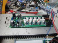
Hi
It look like these capacitors no longer on the PC board (red arrows)
Am I right about that?
I plan to build the BJT version
greetings
Correct, on the new layout those are not present.
I seem to remember there being an error on the screen print and I meant to note it but now I can't remember. Is there a Sprint file or gerber posted somewhere for these new OPS boards? I would like to investigate it a little.
Thanks, Terry
that was just the R108/109 thing , corrected on the schema.
All is perfect - mine are built (and tested). Just need to tap !
OS
just to be sure...
R102/108 22k
R101/109 470r
Hi Evan,
On the board, R108 goes between Q102B and the rail. The schematic shows that resistor as R109 (470R). On the board R109 goes between Q102B and ground. On the schematic, that is R108 (22k). I don't think the screen print is correct. The schematic should be changed to match the boards and posted somewhere for all to see so those are not reversed. What you have just posted is not correct.
It should be;
R102/R109 22k
R101/108 470R
Blessings, Terry
- Status
- This old topic is closed. If you want to reopen this topic, contact a moderator using the "Report Post" button.
- Home
- Group Buys
- SlewMaster Project Boards