How about some more listening comparisons between VFA and CFA amps?
THx-RNMarsh
Richard, just recent impressions - auditioning the hybrid with tube LTP at the input - classical VFA in terms of NFB arrangement - outstanding bass. Powerful, tight, low distortion - very comfortable one any any level.
Cheers,
Valery
Very nice boulding !My stereo build of Slewmaster
Thanks uncle Os.. it'st rock")
Regard Alcroner
Terry, Jason and All - here we go:
Redesigned compensation - the one I could not break
Terry, please use the "lamp tester" in the beginning. I'm sure it's going to be fine this time, but you know... some extra caution will not be excessive.
Jason, your possible additional ideas are always appreciated.
Cheers,
Valery
Didn't work for me. See my explanation in the linked thread.
Well I have done more listening of my CFA-XH BV2 and although I cannot do a direct comparison I would definitely say it sounds better than the blameless that preceded it. Of course take that with a grain of salt because I cannot double blind test it or anything.
In what way does it sound better?
-RM
Richard, just recent impressions - auditioning the hybrid with tube LTP at the input - classical VFA in terms of NFB arrangement - outstanding bass. Powerful, tight, low distortion - very comfortable one any any level.
Cheers,
Valery
OK, Check. Also classic sound quality for that topology.
-RM
In what way does it sound better?
-RM
Clearer, better resolution especially in the treble, things sound 'finer' if that makes sense
Sounds seem to fade away more and stop more precisely than before.I am not one for subjective mumbo jumbo and I'd like to know what to attribute to this difference in perceived sound quality. I mean this amplifier has a completely different compensation scheme, fully regulated input stage, is a CFA vs VFA, is probably faster than the previous design, has a symmetrical input stage, has RC filtering in a number of places and has two pairs of output transistors per channel rather than just one pair. These are driving benign 4 ohm loads and going to two pairs does reduces large signal non linearity. I mean the amplifiers are technically superior in a number of ways, so there are good reasons for it to sound better.
Clearer, better resolution especially in the treble, things sound 'finer' if that makes sense
Welcome to CFA world, resolution (single subtraction device) and speed (current on demand). Even simple six transistor CFA design sounds superior than complex VFA.

I need to get my second PSU completed so I can do a solid all Slewmaster A/B comp setup. I have 4, 5 pair OPS mounted on two huge heatsinks and two identical 55-0-55vac transformers. I only have one filter bank for it. Now that I have a break from building IPS boards I should concentrate on getting another filter bank built. Then my dual test setup can be completed. Hopefully just in time for OS's return. He claims he has a bunch of new IPS designs. 
Welcome to CFA world, resolution (single subtraction device) and speed (current on demand). Even simple six transistor CFA design sounds superior than complex VFA.
Translation: buy my VSSA kit.
Got a Symasui board stuffed today for QC check. Looks good so far, just need to get an appropriate op-amp for the servo tomorrow.
Hi Jason,
My boards should arrive today. I have a question about the 2.2u caps C1 and C13. Can those be electro and if so, which way should the polarity face?
Thanks, Terry
Attachments
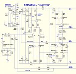
It is not simpler (better) to ommit whole servo circuit and instead this put simple capacity (electrolytics, AC voltage across cap few mV, no distortion) about 220uF in series with R25? You get 100% DC NFB, and output ofset will be in mV region (caused only by h21 unbalace Q1,Q2,), no servo needed. Now is here DC bias resistor unbalance R25//R24 vs R2, and resulting input ofset voltage is amplified by amp gain, than corrected by servo..A bit strange and complicated.
Last edited:
Hi Terry use 2x1uf film for eatch position.Hi Jason,
My boards should arrive today. I have a question about the 2.2u caps C1 and C13. Can those be electro and if so, which way should the polarity face?
Thanks, Terry
Thimios.
You can use 1uf and then you must change R26,27=1MThat'll work. Thanks
My symasui is here.http://www.diyaudio.com/forums/solid-state/248105-slewmaster-cfa-vs-vfa-rumble-165.html
Thimios.
Last edited:
- Home
- Amplifiers
- Solid State
- Slewmaster - CFA vs. VFA "Rumble"