I just tried it and the bias adjusts no problem. With a 3k3 resistor and the bias dialed all the way down, (clockwise) I see 1V at PD. With the bias raised to 13mV across two a pair of emitter resistors I see 1.3V at PD. I didn't try hooking up an IPS but I'm pretty sure it will play.
I have 150R in R113 to cool down the drivers a little. All other values are per schematic.
Hope this helps
I have 150R in R113 to cool down the drivers a little. All other values are per schematic.
Hope this helps
Thanks Terry. Mine are in the same ballpark but 1.5 mV across the emitter resistors. My circuit seems to be operating then. Just not able to supply enough current. I'm stuffing a 2 output board to compare now.
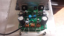
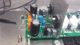
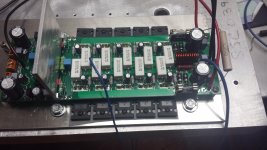
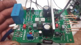
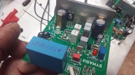
Post a decent picture of the OPS so we can have a quick look and maybe catch something amiss.
OK I see, your supply is being pulled down. I'm using a 400VA toriod.
I'm using a toroid from an old Arcam amp. I think it's around 400 VA but it really drops off from open circuit voltage. Down to 32V with any kind of load. It's the 12 volt rail in the input section that drops off to 8 volts.
Post a decent picture of the OPS so we can have a quick look and maybe catch something amiss.
Will do.
I think the Symasui is actually working correctly. I think it's just dragging itself down trying to feed the output board. It seems to operate fine standalone. I was stuffing a 2 pair board to test with until I realized I didn't have TO220 drivers. I'll be back at the office tomorrow. I'll stuff another 5 pair board and test. I'll post some pictures then too.
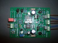
Here is a picture of a Symasui that I know works.
Would Q9/10 need to be match at all?.
Quan
The IPS should work with the output shorted to the NFB. How can the OPS put any more load on it than a direct short? I would double check to see that you have the correct transistors in each location and that they are oriented correctly. I still think there is something wrong. The zeners set the front end of the IPS to 12V Unless the rail drops below that it should maintain 12V. It feed the bases of Q3, Q4, Q5 and the servo. Those are all P channel A992. My guess is one of those is wrong.
EDIT; It is also vital that the NFB is connected.
EDIT; It is also vital that the NFB is connected.
Last edited:
OK, sorry I didn't try this earlier. I just hooked my Symasui IPS to the OPS and fed it +-30V. It won't light D5 but it does light D6. Voltage at -ND is 305mv and +PD is 1.025. Keep in mind that I have 4k7 in R11 so I don't know what would happen if I put 1k5 in there. The Wolverine will play at 30V but maybe not the Symasui without some value changes. Someone more educated will have to help with that. I suppose I could temporarily parallel a resistor to R11 to see if that will help.
Have you connected the two G2 points on the OPS?
Yes I did. I connected them to the G2 point on the input board too. I assume they are supposed to connect to ground separately from the star ground?
Actually the star on the IPS doesn't get a connection outside its connection the the connector at the edge of the board, it forms a star-on-star arrangement. It shouldn't cause ant functional issue if a wire is connected there.
Does the +V and -V off the OPS stay within a couple of volts of the raw supply voltage? That is to ask are the capacitance multipliers working alright?
Does the +V and -V off the OPS stay within a couple of volts of the raw supply voltage? That is to ask are the capacitance multipliers working alright?
- Home
- Amplifiers
- Solid State
- SlewMaster Builds