Will do then report back .You don't appear to have installed any output devices yet. Without those there will be no current flow through any of the 0R22 resistors. If you want to play it safe, put in one pair and test that prior to installing the rest.
Quan
Hi Jason, installed one pair of ouput BJT but still no luck. I used rail 45+/-, resistor simulate vAS of 8.8Kohm. The DC offset was 5Vc and no flow of current through the output BJT. I think i must have installed one of the trannies incorrectly.You don't appear to have installed any output devices yet. Without those there will be no current flow through any of the 0R22 resistors. If you want to play it safe, put in one pair and test that prior to installing the rest.
Quan
Yes, do re-check your parts installation before we dive off the deep end into trouble shooting. Offset should be in the perhaps tens of mV (no feedback mechanism to correct it) and with a simulated VAS current it should bias up. strange that you were reading relatively high currents in the pre-driver / driver yet can't develop bias current into the outputs.
You have everything with a metal tab insulated from the heat sinks?
You have everything with a metal tab insulated from the heat sinks?
Yeah, i made sure of insulation of all required trannies.Yes, do re-check your parts installation before we dive off the deep end into trouble shooting. Offset should be in the perhaps tens of mV (no feedback mechanism to correct it) and with a simulated VAS current it should bias up. strange that you were reading relatively high currents in the pre-driver / driver yet can't develop bias current into the outputs.
You have everything with a metal tab insulated from the heat sinks?
Quan
Today i swapped out the predriver trannies(ebay measured HFe 18 whereas digikey measured 89). The Dc offset measured at 3V but excessive current flow through the output BJT . I measured 0.7V across the 0.22R RE and my trafo went to almost melt down mode and shaking like crazy. I went through and double check all trannies regard position-all ok. I am not sure what to do next.
Quan
Quan
OK, sounds like there may be an issue with the bias circuit (Q103 & Q104, R103-107).
Remove the test resistors and short the PD and ND together. There should be no current flowing in the OPS, so no voltage over R110, R113 or the 0R22 emitter resistors of your output devices. If this is so, then we can feel pretty sure there is an issue with the aforementioned bias components. If current still flows then there is something else going on. Please use a bulb limiter during trouble shooting.
Remove the test resistors and short the PD and ND together. There should be no current flowing in the OPS, so no voltage over R110, R113 or the 0R22 emitter resistors of your output devices. If this is so, then we can feel pretty sure there is an issue with the aforementioned bias components. If current still flows then there is something else going on. Please use a bulb limiter during trouble shooting.
OK, sounds like there may be an issue with the bias circuit (Q103 & Q104, R103-107).
Remove the test resistors and short the PD and ND together. There should be no current flowing in the OPS, so no voltage over R110, R113 or the 0R22 emitter resistors of your output devices. If this is so, then we can feel pretty sure there is an issue with the aforementioned bias components. If current still flows then there is something else going on. Please use a bulb limiter during trouble shooting.
Yeah Jason . The bulb limiter has been on my list to do for a while now. I will have to gather parts over week end then report back then.
Quan
Yes, the bulb limiter is a very important piece if gear. A quick trip to a hardware store should get you what you need. I recently assembled a board where I installed to outputs in the opposite locations and it would have blown up if the limiter hadn't alerted me to some major issue.
I also suggest getting a modest transformer for initial testing too. Say something like a 24-0-24 VAC and <200VA so it will make for a little softer supply. Mine is dual 22V secondaries @160VA for testing.
I also suggest getting a modest transformer for initial testing too. Say something like a 24-0-24 VAC and <200VA so it will make for a little softer supply. Mine is dual 22V secondaries @160VA for testing.
Yes, the bulb limiter is a very important piece if gear. A quick trip to a hardware store should get you what you need. I recently assembled a board where I installed to outputs in the opposite locations and it would have blown up if the limiter hadn't alerted me to some major issue.
I also suggest getting a modest transformer for initial testing too. Say something like a 24-0-24 VAC and <200VA so it will make for a little softer supply. Mine is dual 22V secondaries @160VA for testing.
I am using +/-30VDC 120VA for testing purposes only. I remember about the incorrect outputs on the other thread . I have been lazily just using the variac only but this does not limit the currents so not much of warning and potentially can destroy the amp /testing device completely.
Quan
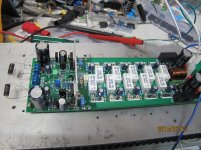
Quan, I was just looking at your picture in post 118. Is Q106 installed correctly? From that angle I'm looking at the back of my transistor.
Yes Wilm, you are looking at the back of mje350. My understanding is ECB looking at the front of the transistor which is the same as mje340?.
Quan
Yes Wilm, you are looking at the back of mje350. My understanding is ECB looking at the front of the transistor which is the same as mje340?.
Quan
My MJE350 has metal showing on the back side. Yours must be fully insulated.
Yes, the TO-126 are ECB. Are your MJE340/MJE350 a full plastic package? Most seem to have an exposed metal back and maybe that is what jwilhelm was looking for.
Yes ,they are TO-126-fully plastic.
Quan
- Home
- Amplifiers
- Solid State
- SlewMaster Builds