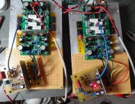
The Slewbaby is playing!!!! I hooked it to my home etched Wolverine IPS. Really sounds lovely. I have a question about SOR. I never understood how to measure that. I'm using MJL4281/4302 for my outputs. What is the highest voltage I can use into 4 ohms and still be OK? Right now, I am using a variac to hold it at about +-54V. It is running nice and cool with the bias set to 25mV across a pair of emitter resistors. I would like to go up in voltage some if I can but I need to know about the SOR.
Thanks, Terry
Thanks, Terry
Attachments
For a 'Rule of Thumb' I have seen the following suggested:
Add up the total maximum device dissipation and divide by five (or six for a more conservative number) to get the maximum average power that can be expected. Use the power figure and your nominal impedance to calculate the required output voltage to achieve that output power. I would then personally use an educated guesstimate to account for power supply sag and losses to get the idle rails. I generally assume about 10-12% in total losses under full load from unloaded.
This might seem conservative but let's look at the numbers when talking about a 4 Ohm load:
4x 230W devices = 920W total dissipation
920W / 5 = 184W of expected output power capability
184W x 2 = 368W of peak power output (remember the 184W is average, or erroneously quoted as RMS power)
We know that P=V^2/R, so shuffling things around and solving for V we get a required output voltage of 38.4V peak.
Let's say we loose a total of 12% between the PSU and output stage voltage losses, so we target unloaded rails of about 43V. Convenient transformer values (like a 300-500VA 30-0-30 VAC transformer) would usually give us 45v rails.
The same calculations with an 8 Ohm load gives rails more like 60V, just for interests sake.
Last edited:

That's what I was afraid of. Nothing wrong with that except that just puts it in the same realm with all the other small amps I have but with a much larger footprint. I guess it does have the advantage of accepting different IPS topologies. I'll compare it to the Ovation nx and see how it does.
Blessings, Terry
Blessings, Terry
Thanks Jason, my second board is good to go. The DC offset now is 1mV and set bias at 75mA. The 2OPS/symasui are next.Bring the OPS to 10mA or the minimum you can get if it doesn't go that low when connecting the IPS for the first time. On the CFA-XH, centre the adjusters as a preset. Use the adjusters to get minimal offset and then adjust the OPS bias. The actual VAS current has a limited range and will be in the ballpark with the adjusters centred. Try that and see how it goes.
The testing procedures for checking the sections individually is just for verification, when joined together they should be setup together.
Quan
Another good thing about building the baby slew was that while testing it I discovered that the oscillation issues I was having with one of my Slewmonster boards had damaged one of the previously good CFA-XH IPS boards I was using. The new baby slew showed that which is why it was being tested with the Wolverine boards above. So today I hooked up the Wolverine boards to the Slewmonster boards and the oscillation is gone. Very happy. It's cool that Jason is tackling the Wolverine next. It is really really good sounding, as a Blameless should be.
Jason watch here. "920W / 5 = 184W of expected output power capability "
Should this not be 920/4 = 230Watt for 4 ohm or did miss something !
Honestly I don't know. I have only seen the factor of 5 or 6 used in the 'Rule of Thumb' calculation, depending on how conservative one wants to be.
If you can find a reference to what factor is good for nominal impedance that would be good.
Last edited:
That I don't doubt. We would have to put a load line on a combined SOA graph to see what a given number of pairs is capable of with appropriate temperature de-rating.
The oft quoted design rule I'm sure makes certain assumptions and almost certainly errs on the side of being conservative.
The oft quoted design rule I'm sure makes certain assumptions and almost certainly errs on the side of being conservative.
Hi Jason . With regard to Symasui build those C9/10/11/12 capacitors 01.uf - can i use 0.22uf, also the 33pf-would 47p be ok?
Quan
Those substitutions are fine, the 0.1uF are just decoupling the power supply so any small value cap is fine, even the much maligned ceramic would do. The 47pF will just increase the amount of compensation some but shouldn't cUse any problems at all.
did any of you builders accidentally shorted the speaker wires and did your amp survived?
I did

My speaker protector output is shorted to ground when it is not working. I connected amp output to speaker protector output, and speaker to speaker protector input. When power up, in few second amp output shorted to ground. Fuse on power supply was burn but my amp survived
I burn many fuse before I found the fault
Is it possible to test a 5 pair output stage with 30 volt rails? I can't get any bias current to flow.
What method are you using to test it? I can hook mine up to a variac if you need. Are you using 18k resistors from +<PD and -< ND or do you have an IPS attached?
- Home
- Amplifiers
- Solid State
- SlewMaster Builds