The capacitance at each Aleph emitter is really Qg of the MOSFET gate.
Has to be charged and discharged every cycle. More cycles, more loss.
The comparator BJTs are conveniently not wired to give any assist,
and neither the CCS...
If the CCS are complimentary JFETs, you can tap halfway into Iset
source resistors and get a little bit of "antitriode style" boost. Or go
all the way up to the source "mu follower style", but the slew assist
here might be assymetrical. Actually, if the source follwer impedance
is significant, the true "center tap" of the external Iset resistor might
be closer to the top end than the center.
Pass had warned me that MOSFET capacitance is a highly nonlinear
event, worse in this circuit than the bootstraps, and overlooked in
most simulator models. We can rely upon the BJT to compare away
any voltage error, but it can't compare away the drive current.
kenpeter said:The capacitance at each Aleph emitter is really Qg of the MOSFET gate.
Has to be charged and discharged every cycle. More cycles, more loss.
The comparator BJTs are conveniently not wired to give any assist,
and neither the CCS...
If the CCS are complimentary JFETs, you can tap halfway into Iset
source resistors and get a little bit of "antitriode style" boost. Or go
all the way up to the source "mu follower style", but the slew assist
here might be assymetrical. Actually, if the source follwer impedance
is significant, the true "center tap" of the external Iset resistor might
be closer to the top end than the center.
Pass had warned me that MOSFET capacitance is a highly nonlinear
event, worse in this circuit than the bootstraps, and overlooked in
most simulator models. We can rely upon the BJT to compare away
any voltage error, but it can't compare away the drive current.
I see. I was worried about the MOSFET models.
Your suggestion on the MOSFET drive is insightful. If the simulator is to be trusted in this case, the input impedance of the MOSFETs is far more linear than if we used BJTs in the same position. But I must be open that this might not be the case.
Thanks,
- keantoken
kenpeter said:Resistor drops in series with emitters Q5 and Q6 might be able to
close the diamond even tighter...
Good idea. But if we do this, Vcb for the main Allison transistors become smaller. In order to keep from distorting, we would have to convert to Darlington outputs. So far in simulation this isn't very promising stability-wise.
That seems like overkill to me, where we might as well leave out the MOSFETS at that point, because a decent VAS and input stage will allow us to get very low distortion without the HF impedance of the MOSFETs (unless we compensate for that somehow...).
But anything is worth trying.
This is what I have.
- keantoken
Attachments
On a side note, I redid one of my previous incarnations of the Allison.
With this one you can adjust bias voltage with the emitter resistors of Q5 and Q6 (as suggested by Kenpeter). My previous notion of putting the emitter resistors on Q7 and Q8 was a really, really bad idea because it amplifies the distortion produced by the output devices' base currents. The diodes in their place bump up the bias voltage to .6V, which is cut down by the emitter resistors. These diodes themselves produce a small amount of distortion (probably insignificant). If you're worried enough, you should bypass them with a good cap.
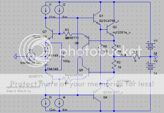
Here is the old version. I did some experimenting with the extra cap. If anything, I think it actually improves stability, but I haven't tested it. Theoretically, this cap is more effective against 3rd harmonics than 2nd harmonics (specifically, it should be half as effective against 2nd harmonics)... So if we purposefully used different drivers for the output transistors, we might actually be able to inject some H2... Still, this is theoretical, so maybe I'm wrong.
- keantoken
With this one you can adjust bias voltage with the emitter resistors of Q5 and Q6 (as suggested by Kenpeter). My previous notion of putting the emitter resistors on Q7 and Q8 was a really, really bad idea because it amplifies the distortion produced by the output devices' base currents. The diodes in their place bump up the bias voltage to .6V, which is cut down by the emitter resistors. These diodes themselves produce a small amount of distortion (probably insignificant). If you're worried enough, you should bypass them with a good cap.
Here is the old version. I did some experimenting with the extra cap. If anything, I think it actually improves stability, but I haven't tested it. Theoretically, this cap is more effective against 3rd harmonics than 2nd harmonics (specifically, it should be half as effective against 2nd harmonics)... So if we purposefully used different drivers for the output transistors, we might actually be able to inject some H2... Still, this is theoretical, so maybe I'm wrong.
- keantoken
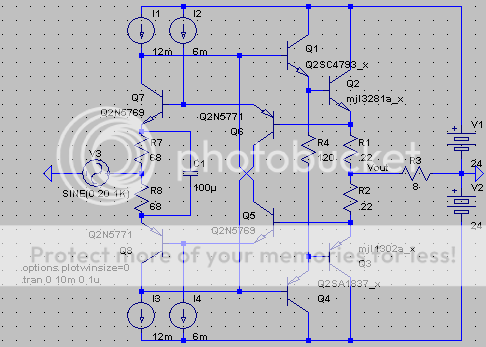
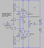
Notice: I turn your favorite CCS all basakwerdz and abuse it as an
50% active current source. Also helps slew symmetry to the gates.
I had depletion JFETs in that duty before, these are much better.
Lowest distortion yet, and hits 96KHz no prob...
I still need to check how it misbehaves in AB and clipping.??
50% active current source. Also helps slew symmetry to the gates.
I had depletion JFETs in that duty before, these are much better.
Lowest distortion yet, and hits 96KHz no prob...
I still need to check how it misbehaves in AB and clipping.??
Attachments
kenpeter said:Re-Biased and Schottky'd up for super smooth AB crossings.
Not sure why? But clipping is much better behaved when the
bootstraps are fed from the same node as the final output...
Your cct is open loop wrt OP bjts.
The whole idea of Allison cct is to have OP devices 'in the loop' so to
speak.
Am I missing something here?
T
Terry Demol said:
Your cct is open loop wrt OP bjts.
The whole idea of Allison cct is to have OP devices 'in the loop' so to
speak.
Am I missing something here?
T
The MJL outputs form an emitter follower/buffer from the output. This will cause distortion.
Unless someone can put up Allison's original article, we'll never know what he was thinking.
- keantoken
Maybe I spoke too soon. Kenpeter's circuit does perform pretty well.
Ken, can you list what exactly you're designing for? I'm designing for:
1: low distortion.
2: linear input impedance.
3: low input impedance.
If you told me your aims I would be able to look at your circuit from a less vague standpoint.
Also, Ken, on your circuit:
Since the bootstraps are taken from the Allison output, your gain will be affected.
- keantoken
kenpeter said:Re-Biased and Schottky'd up for super smooth AB crossings.
Not sure why? But clipping is much better behaved when the
bootstraps are fed from the same node as the final output...
It might be because when you take bootstraps from the Allison output (as opposed to your final output), you load the allison itself. When your bootstraps are affected by clipping, this injects the clipping signal into the allison, injecting the signal back through the entire circuit.
The same principle would work with distortion. This is why I wouldn't use the Allison output to drive bootstraps, since the Allison is actually a very important part of the circuit. That is only my preference though.
I found a decrease in distortion if you connect the Allison output with the final output.
- keantoken
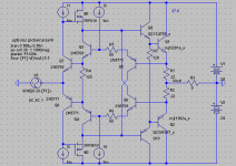
A note on bootstraps
I have been messing around with the Allison and bootstraps.
Note the position of the bootstraps.
Bootstrapping from the direct output in this case is not ideal because we want a constant voltage across R5 and R7. Thus, we want to bootstrap from whatever place has the most constant voltage relative to the MOFETs' gates. This point turned out to be the Sources. This gives BETTER performance than the two-transistor CCS I usually use.
Secondly, note that the bootstraps are referenced from the sources on the complimentary sides. This provides better cancellation of 2nd harmonics (thus preferring odd harmonics). If we switched the bootstrap references, even harmonics would be preferred.
I'm not sure what objective advantages/disadvantages there are from switching the bootstrap references, apart from which harmonics you prefer.
- keantoken
Attachments
Terry Demol said:
Your cct is open loop wrt OP bjts.
The whole idea of Allison cct is to have OP devices 'in the loop' so to
speak.
Am I missing something here?
T
That would be Hawksford: single error correcting feedback from
the output node. Allison: two independant error correcting amps,
emitter coupled, with some voltage offset spanned between them.
Closed without feedback, as one would close a diamond buffer....
I could cross connect the center of both drives and output, and
net two feed backs that are weighted/blended behavior between
Allison and Hawksford....
keantoken said:A note on bootstraps
I have been messing around with the Allison and bootstraps.
Note the position of the bootstraps.
Bootstrapping from the direct output in this case is not ideal because we want a constant voltage across R5 and R7. Thus, we want to bootstrap from whatever place has the most constant voltage relative to the MOFETs' gates. This point turned out to be the Sources. This gives BETTER performance than the two-transistor CCS I usually use.
Secondly, note that the bootstraps are referenced from the sources on the complimentary sides. This provides better cancellation of 2nd harmonics (thus preferring odd harmonics). If we switched the bootstrap references, even harmonics would be preferred.
I'm not sure what objective advantages/disadvantages there are from switching the bootstrap references, apart from which harmonics you prefer.
- keantoken
Class AB crossings can be real glitchy in that configuration.
Rewind to my earlier designs, you see I was strapped at
that very same location. Stopped doing that for a reason.
Energy stored in the cap allows the Transistor to turn off
too hard... Even in AB it shouldn't never quite turn off...
OK, its a MOSFET, doesn't have a carrier storage. But locked
in the Allison loop, the drive signal glitches hard when it can't
make the Transistor behave as expected... And that stores
on the Gate capacitance.
In full Class A, you maybe aren't seeing the issue.
kenpeter said:
Class AB crossings can be real glitchy in that configuration.
Rewind to my earlier designs, you see I was strapped at
that very same location. Stopped doing that for a reason.
Energy stored in the cap allows the Transistor to turn off
too hard... Even in AB it shouldn't never quite turn off...
OK, its a MOSFET, doesn't have a carrier storage. But locked
in the Allison loop, the drive signal glitches hard when it can't
make the Transistor behave as expected... And that stores
on the Gate capacitance.
In full Class A, you maybe aren't seeing the issue.
I see. Personally, I would limit the output current at an earlier stage so as not to clip the Allison. But there is no harm in being careful.
- keantoken
Smooth misbehavior in clipping and AB crossing.
No glitches, no rings, no oscillations whatsoever.
Low low distortion at 1W in 8 ohms (20-20KHz)... 90db down.
96KHz sinewave in recognizable as a 96KHz sinusoid out.....
Slew reasonably clean (some squashing distortion OK) +/-23V
Reasonably flat 47K input impedance.
Low parts count.
25V rails
No glitches, no rings, no oscillations whatsoever.
Low low distortion at 1W in 8 ohms (20-20KHz)... 90db down.
96KHz sinewave in recognizable as a 96KHz sinusoid out.....
Slew reasonably clean (some squashing distortion OK) +/-23V
Reasonably flat 47K input impedance.
Low parts count.
25V rails
kenpeter said:
That would be Hawksford: single error correcting feedback from
the output node. Allison: two independant error correcting amps,
emitter coupled, with some voltage offset spanned between them.
Closed without feedback, as one would close a diamond buffer....
I could cross connect the center of both drives and output, and
net two feed backs that are weighted/blended behavior between
Allison and Hawksford....
Yep got it now.
Looks interesting, I'll run the sim up later.
cheers
T
And making the output and feedback center nodes connect
does seem to reduce 1W distortion with no bad side effects.
Blend under test today: roughly 1/3 Hawksford, 2/3 Allison...
No component changes necessary from the previous schematic.
Though I have found that both R5's of my bootstrap could easily
be increased to about 1K8 without starving the active current
sources. It has a negligible effect on distortion, but may let the
TO92 parts run cooler...
I've also messed with a secondary set of output transistors
outside feedback, just to pump the bootstraps only... This also
had a surprisingly negligible benefit, no way to justify the extra
parts....
keantoken said:A note on bootstraps
I have been messing around with the Allison and bootstraps.
Note the position of the bootstraps.
This gives BETTER performance than the two-transistor CCS I usually use.
- keantoken
Plain CCS and/or plain bootstrap don't offer any help in driving.
All the drive current swing has to come from the input. And the
drive swing seems to be the limiting factor on input impedance.
And plain bootstraps are sensitive to power fluctuations, but
that can be abused as a soft limiting "feature" as well...
Now you turn a CCS around and let it help take a symmetrical
50% of the burden. The input impedance almost doubles. Yes,
you now have some additional loss to drive the active current
source's base (through it's comparator's emitter), but a lot less
than the help it gives in return.
Just not sure how to replace the soft limiting that disappears
anytime a current source regulates the bootstrap. If I starve
my current sources (active or not) below where they regulate,
they don't soft limit clipping as expected... This formula seems
to aggravate an oscillation....
- Status
- This old topic is closed. If you want to reopen this topic, contact a moderator using the "Report Post" button.
- Home
- Amplifiers
- Solid State
- Simulation Analysis of several unique Allison-based output stages.