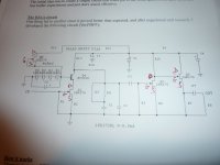
Today I finished replacing the 15,7 SM for 15,33 on my old 48dB build and now I have an issue.
Left channel does not work... Leds do not lit, so I removed the board and tryed to lit up the leds using a 9v baterie over the ccs fet. I could not lit the leds so I lifted gnd below the leds and they lit.
Something is wrong because the leds only work if not connected to star gnd.... It seems there is some short circuit
Is there any component in the second stage that could cause a short between +v and GND ?
Last edited:
The sound now is more clear but seems lose gain, still needs more body & right channel need to lower to 15nF to have more highs, the right channel it's OK for highs also I suspect that now I have less body cap because interstage cap was changed now I have 0.047uF 200V instead 0.1uF 600V, what do you think?
Today I finished replacing the 15,7 SM for 15,33 on my old 48dB build and now I have an issue.
Left channel does not work... Leds do not lit, so I removed the board and tryed to lit up the leds using a 9v baterie over the ccs fet. I could not lit the leds so I lifted gnd below the leds and they lit.
Something is wrong because the leds only work if not connected to star gnd.... It seems there is some short circuit
Is there any component in the second stage that could cause a short between +v and GND ?
Wich schematic do you use Ricardo, I will check the nearest transistor to Leds.
Absolutely I prefer jumper instead R9 & disconnect C5 (thank you Nick
Now that you are free of this RC, you can tune the tone just by choosing the best combo on the shunt´s output and vref
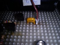
0.1uF FT-3 Teflon cap Vref several weeks ago upgraded, recently upgraded resistor Vref with a Vishay VSH1 290R
What does the FT-3 bypass ? Output or vref ?
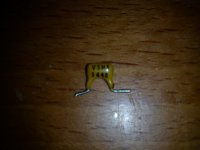
What are those big black fims made of ?
Hi all,
Im planning the build of a second Simplistic RIAA to implement several of the changes that have been suggested since my first effort.
I have the 10.12.F0 document (is this the latest?) to follow, though I can't easily find recommendations on what filtering is best after rectification. My first Simplistic just had a single 15,000uF can into a single Salas Shunt for both channels. Is there a better configuration that I should try for my second shot? I'll be using 2 Salas shunts (1 per channel) in this build, but only 1 transformer... unless I get convinced otherwise. Are 2 separate bridge rectifiers worth trying?
I realise that this has probably been covered recently, though there are many, many posts and searching didn't expose what I was looking for. Your help is greatly appreciated, as always.
Regards,
Tani.
What does the FT-3 bypass ? Output or vref ?
What are those big black fims made of ?
1. Vref
2. Are Mundorf polypropylene tin foil in Salas LV shunt reg V1.2R
I used two resistors to get the desired voltage. I will try your suggestion if I find one. Thanks
Michael Percy has the Vishay trimmers.
Web http://www.percyaudio.com/Catalog.pdf
E-mail mpercy@pacbell.net
Hi all,
Im planning the build of a second Simplistic RIAA to implement several of the changes that have been suggested since my first effort.
I have the 10.12.F0 document (is this the latest?) to follow, though I can't easily find recommendations on what filtering is best after rectification. My first Simplistic just had a single 15,000uF can into a single Salas Shunt for both channels. Is there a better configuration that I should try for my second shot? I'll be using 2 Salas shunts (1 per channel) in this build, but only 1 transformer... unless I get convinced otherwise. Are 2 separate bridge rectifiers worth trying?
I realise that this has probably been covered recently, though there are many, many posts and searching didn't expose what I was looking for. Your help is greatly appreciated, as always.
Regards,
Tani.
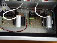
I use two R-Core Tx, two rectifiers Stealth II with two BG 10.000uF & two Salas LV shunt reg V1.2R & sounds very good
Questions
Hi, Salas,
I have built your phono stage for MM cartridge. I use the phono stage with transformers Sowter 9580 with Denon DL103; the sound is very good.
But I have some questions for you:
I have used for the shunt regulator and phono stage N°11 red Led (V1.85), but the measuring gave only V1.62. I have to add more LEDs?
My Jfet 2SK170BL are matched to 7.5mA. I have to replace them with between 8-8.5 mA or should substituted other components?
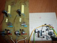
Attached schematic positioning and photo of JFET in phono stage. It's correctly? Because i have seen in other schematic of people that have built the phono stage, the Jfet mounted wrongly (Drain and the Source reversed).
Many thanks.
Mario.
Hi, Salas,
I have built your phono stage for MM cartridge. I use the phono stage with transformers Sowter 9580 with Denon DL103; the sound is very good.
But I have some questions for you:
I have used for the shunt regulator and phono stage N°11 red Led (V1.85), but the measuring gave only V1.62. I have to add more LEDs?
My Jfet 2SK170BL are matched to 7.5mA. I have to replace them with between 8-8.5 mA or should substituted other components?
Attached schematic positioning and photo of JFET in phono stage. It's correctly? Because i have seen in other schematic of people that have built the phono stage, the Jfet mounted wrongly (Drain and the Source reversed).
Many thanks.
Mario.
Attachments
- Home
- Source & Line
- Analogue Source
- Simplistic NJFET RIAA