tricky? no.salas said:
What do you see in my sim pic post? 11.45mA centre and AC hovers around. So you answered it. Drain is virtually AC grounded, remember. So we avoid an extra capacitor between 2nd stage and buffer, or a symmetric supply. Tricky Salas, shame on you.
The quiescent state is 11.45mA and this is ~150% of Idss if you chose 7.5mA Idss as your device.
AndrewT said:and I cannot recall anywhere that recommends running the Id=150% of Idss.
The B1 in optimum state certainly doesn't and cannot be used as a valid reference for your design choice.
It can be as for the chosen voltage across, for the chosen Idss device and the way it distorts, not for the current quiescent condition. I refer only to the voltage across. Of course I use more current. Posted simulator pics that clearly show. If you feel like relaxing it I also posted values to Jonners for 6.6mA. But it works, and works nicely. 2 examples made.
AndrewT said:tricky? no.
The quiescent state is 11.45mA and this is ~150% of Idss if you chose 7.5mA Idss as your device.
Semantics. Say not tricky, say non conservative.
I would but its not nice, since I did it. I have B1 too to compare. Maybe Lee can, since he uses an example of mine. Of course the buffer choice is open, someone can strap a B1 style buffer or white follower Njfet style buffer a la Borberly. No reason to follow strictly my practices there.
Neg Led PSU bro
So, some may explore other buffers, which may need symmetric supplies.
Also Nicoch has asked for a negative PSU some time ago. Someone from the B1 thread asked too.
Here I post the symmetric neg ones. Haven't made any, I have no use, they should work nicely as mirror images since the positive already works with no problems.
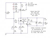
The first one is the negative of the one that uses 2SK for the LED CCS. Alas, the 2SJ74 is 25V limited, so we can't exceed Vin-VLeds>25V.
So its good if you have some 2SJ74s in your stash and you are using a capacitor less B1 buffer or something else using up to +/- 20-22V.
So, some may explore other buffers, which may need symmetric supplies.
Also Nicoch has asked for a negative PSU some time ago. Someone from the B1 thread asked too.
Here I post the symmetric neg ones. Haven't made any, I have no use, they should work nicely as mirror images since the positive already works with no problems.
The first one is the negative of the one that uses 2SK for the LED CCS. Alas, the 2SJ74 is 25V limited, so we can't exceed Vin-VLeds>25V.
So its good if you have some 2SJ74s in your stash and you are using a capacitor less B1 buffer or something else using up to +/- 20-22V.
Attachments
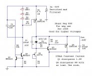
And the second one. This uses a Wilson current source for the LEDs. 60V ''ring of two'' transistors can be used higher. I simulated the symmetric of the page 16, post #399 Cygnus X1 example.
You know by now, scale the Zener, use 6-8 -Vin more than -Vreg, for your chosen voltage, which is Vz+Vbe or about, depending on Zener's tolerance to its nominal value. The LEDS must be measured for the string of 3 Vdrop. ICCS=(LEDSVdrop-3.4)/R1.
You know by now, scale the Zener, use 6-8 -Vin more than -Vreg, for your chosen voltage, which is Vz+Vbe or about, depending on Zener's tolerance to its nominal value. The LEDS must be measured for the string of 3 Vdrop. ICCS=(LEDSVdrop-3.4)/R1.
Attachments
Example of strapping a B1 buffer
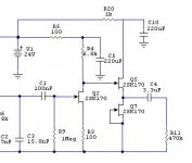
Say you have a difficult input to drive and you want to listen to a B1 Idss type buffer at the Riaa tail. You see to center B1 around second stage's Vd. So you pick 2 matched Idss NJfets (Q5,Q7), and you adjust the Rfeed (R20) to drop enough Voltage so to get VdQ5=2*VdQ2. VdQ5=PSU-Vdrop. Vdrop=Idss*Rfeed. An example on the MM version's tail is attached. But listen to the original hot running source resistor single FET type too. Sounds different.
Say you have a difficult input to drive and you want to listen to a B1 Idss type buffer at the Riaa tail. You see to center B1 around second stage's Vd. So you pick 2 matched Idss NJfets (Q5,Q7), and you adjust the Rfeed (R20) to drop enough Voltage so to get VdQ5=2*VdQ2. VdQ5=PSU-Vdrop. Vdrop=Idss*Rfeed. An example on the MM version's tail is attached. But listen to the original hot running source resistor single FET type too. Sounds different.
Attachments
I'm struggling again, lol.
I etched a board and swapped the parts over from my point to point. Now I only get very faint music with the volume turned right up max.
This is a different setup though, the phono stage is fed into a 50k pot and there is a dicrete buffer stage after the pot.
Any ideas please?
Cheers, Lee.
I etched a board and swapped the parts over from my point to point. Now I only get very faint music with the volume turned right up max.
This is a different setup though, the phono stage is fed into a 50k pot and there is a dicrete buffer stage after the pot.
Any ideas please?
Cheers, Lee.
Give me data. What you did last time, and you got it solved? What was the mistake? Lets start from there. You said something about wrong Idss. Maybe it was more actions? First of all measure your drain voltages on all Fets. Let me know. Also, do you get music if you disconnect the external buffer and drive your line input directly? Your point to point had a buffer, had output from top of R19, maybe you take output connection from the PCB at a point that it is not the drain of Q2 now?
You can laugh as much as you like:
The fets and transistor were the wrong way round
Making music right now. I have a hum, but that's just poor placement of the reg. I shall attempt a shunt reg today. I'll also fit the Russian Silver Mica's and paper in oils.
Thanks for your help, yet again.
Lee.
The fets and transistor were the wrong way round
Making music right now. I have a hum, but that's just poor placement of the reg. I shall attempt a shunt reg today. I'll also fit the Russian Silver Mica's and paper in oils.
Thanks for your help, yet again.
Lee.
- Home
- Source & Line
- Analogue Source
- Simplistic NJFET RIAA