To fully cascode?
After some experience with topology and extended auditioning has been gathered by my friend Michael and me on this Riaa, we can say that using cascode on all stages is giving just different and not necessarily better results. Cascode with BJT sounds more detailed, when just common source sounds less detailed but more fluent. Its a system and recording dependent thing. With push pull amps and multi way speakers, cascode can detract towards hyper detail on some recordings. Its probably serving better SET and full range. MadK urged us in his thread to fully cascode the thing, probably does very good match in his system. Me I will keep on using the 2 stage simple common, I prefer it. My line in is 100k so no buffer.
I guess that a proof mix is what Lee makes. I.e. First stage cascode to preserve detail and can accept any MM cart, second stage just common source not to overcook detail , plus a source follower buffer to keep composure in all driving circumstances.
Hi Salas-
I am starting to gather parts for your shunt reg on post 219 (the first one) to go with your RIAA design on post 110. I'm a bit of a noob to silicon...
I'm trying to source from one supplier (Mouser) here in the US. I've found BC550 and BC560 but with different suffixes; does that matter? Is there a US equivalent to the IRFP9240? Mouser has none.
Caps- I've got some nice little Siemens styrenes for the 47pF and Leclanche styrene for the 100nF. I was thinking about picking up some of those Russian green styrene caps and the FT-1 teflon 1000pF to trim. Any good results with these?
Thanks!
-Kent
Hi Salas -
There's something I don't understand about the component values for the buffer, and since I prefer to understand what I'm doing rather than blindly follow a schematic I wonder if you might help?
Taking your buffer in post 236 as an example: The gate of the buffer fet is presumably at about 8V, same as the drain of Q2. As I understand it, the source has to be more positive than the gate, so the source voltage must be more than 8V. The source resistor is 680R, so the current must be at least 8/680 amps, i.e. 11.8mA. This seems like a lot - is my reasoning correct?
Thanks, John.
kstlfido said:Hi Salas-
I am starting to gather parts for your shunt reg on post 219 (the first one) to go with your RIAA design on post 110. I'm a bit of a noob to silicon...
I'm trying to source from one supplier (Mouser) here in the US. I've found BC550 and BC560 but with different suffixes; does that matter? Is there a US equivalent to the IRFP9240? Mouser has none.
Caps- I've got some nice little Siemens styrenes for the 47pF and Leclanche styrene for the 100nF. I was thinking about picking up some of those Russian green styrene caps and the FT-1 teflon 1000pF to trim. Any good results with these?
Thanks!
-Kent
BC550 and BC560 and IRFP9240 are available from Mouser. The IRFP9240 is replaced with the IRFP9240PbF (lead free version).
Mouser also has styrenic caps -- helps to have their paper catalog. I order from them every week.
The BCs might have some suffix like A, B or C according to the hfe (C is the higher).
If you don't want to use the International Rectifier (now part of the Vishay group) IRFP9240, you can try the Farchild equivalent FQA12P20 (the same now suggested by Nelson Pass for his latest design) available at Mouser.
Both are proudly designed in USA.
If you don't want to use the International Rectifier (now part of the Vishay group) IRFP9240, you can try the Farchild equivalent FQA12P20 (the same now suggested by Nelson Pass for his latest design) available at Mouser.
Both are proudly designed in USA.
the voltage at Q3 base is Zener voltage.jonners said:Taking your buffer in post 236 as an example: The gate of the buffer fet is presumably at about 8V, same as the drain of Q2. As I understand it, the source has to be more positive than the gate, so the source voltage must be more than 8V. The source resistor is 680R, so the current must be at least 8/680 amps, i.e. 11.8mA. This seems like a lot - is my reasoning correct?
Thanks, John.
The Q1 drain voltage ~Zener-600mV.
The source voltage ~33*Id
The gate voltage ~0Vdc.
Vgs=-source voltage
AndrewT said:the voltage at Q3 base is Zener voltage.
The Q1 drain voltage ~Zener-600mV.
The source voltage ~33*Id
The gate voltage ~0Vdc.
Vgs=-source voltage
Hi Andrew.
I get that, but I was actually referring to the last stage, Q5.
John
Hi,
working from the output:
Q5 Id should be < Idss i.e.<=7mA.
Q5 source will be ~ <=4.7V.
Q5 Vgs will be ~<=0v (since it is passing near Idss).
Q5 gate and Q2 drain will be ~ <=4.7V.
Q2 Id will be ~ [36-4.7]/[100+6k8]~=4.5mA
Id = Idss[1-{Vgs/Vp}]^2, take a guess that Vp~-1V and Vgs~-550mV.
Id~=5mA. back to the the guesses and actual Id=4.5mA.
giving Vs~ 150mV (33*0.0045)
It seems that Vgs ~ -540mV and Vd ~ 4.7V
therefore Vg ~ -390mV.
can anyone confirm the calc and logic?
Thanks people for your replies to questions, you covered greatly.
AndrewT explained well for the gain stages. The Q5 buffer is source follower, so its drain is AC grounded. I keep Q5 with 10V across it, which is the optimum I found in my version of Pass B1 (Nelson confirmed to me on the B1 thread that there is an optimum indeed, and has data). A buffer has to be beefy, and that one sounds really good. The dissipation is 113mW so no worries. If you want to relax it at your 36V B+ case, you can use 2.4K feed resistor, 1.2K source resistor, and dissipate 80mW at about 6.6ma and 12V across.
jonners said:Hi Salas -
There's something I don't understand about the component values for the buffer, and since I prefer to understand what I'm doing rather than blindly follow a schematic I wonder if you might help?
Taking your buffer in post 236 as an example: The gate of the buffer fet is presumably at about 8V, same as the drain of Q2. As I understand it, the source has to be more positive than the gate, so the source voltage must be more than 8V. The source resistor is 680R, so the current must be at least 8/680 amps, i.e. 11.8mA. This seems like a lot - is my reasoning correct?
Thanks, John.
AndrewT explained well for the gain stages. The Q5 buffer is source follower, so its drain is AC grounded. I keep Q5 with 10V across it, which is the optimum I found in my version of Pass B1 (Nelson confirmed to me on the B1 thread that there is an optimum indeed, and has data). A buffer has to be beefy, and that one sounds really good. The dissipation is 113mW so no worries. If you want to relax it at your 36V B+ case, you can use 2.4K feed resistor, 1.2K source resistor, and dissipate 80mW at about 6.6ma and 12V across.
AndrewT said:can anyone confirm the calc and logic?
Its not working in isolated DC conditions and its drain is AC grounded. Think in those terms. It actually has 17.7V Vd and 7.8V Vs.
I repeat the questions
are you running Q5 @ 150% of Idss? or using a higher Idss than the 7 to 8mA shown?
AndrewT said:Salas,
are you running Q5 @ 150% of Idss? or using a higher Idss than the 7 to 8mA shown?
Indeed, and as we exchange messages right now it plays at a friend's, driving a 4K7 input pot line stage.
AndrewT said:I repeat the questions
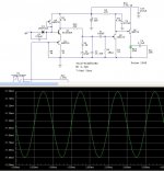
See how it centers there.
Attachments

Did Nelson Pass really say optimum bias is 150% of Idss?salas said:I keep Q5 with 10V across it, which is the optimum I found in my version of Pass B1 (Nelson confirmed to me on the B1 thread that there is an optimum indeed, and has data).
John Curl did say you can run a Jfet at or above Idss. But I think the above was only for the AC content not the quiescent condition.
Most design to run the Jfet Id between 70% and 90% of Idss.
AndrewT said:John Curl did say you can run a Jfet at or above Idss. But I think the above was only for the AC content not the quiescent condition.
Most design to run the Jfet Id between 70% and 90% of Idss.
What do you see in my sim pic post? 11.45mA centre and AC hovers around. So you answered it. Drain is virtually AC grounded, remember. So we avoid an extra capacitor between 2nd stage and buffer, or a symmetric supply. Tricky Salas, shame on you.

- Home
- Source & Line
- Analogue Source
- Simplistic NJFET RIAA