For flat Leds like these examine with a torch light for a wider metal structure inside which is cathode side. Looks like half a tooth and a tiny saucer on top. In circular Leds there's a lip trim in their lens case for cathode side but flat ones give no certain external orientation clue anymore after installed and their legs are cut equal. Shorter leg is cathode in all Leds as they come from manufacture.Will check in the morning the led orientation and functionality.

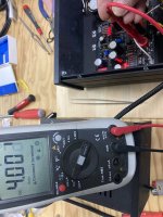
I‘m having more luck. Set to LoMC, 100 ohm load, biasing to the mV (between 3.97 / 4.02 V at t.p.). At first t.p. showed 0 and I started to panick, then to turn the trimmer et voila!
Sad thing is that I won’t be able to listen to it, as I‘ll be away for a week (EEK, A WEEK!)
Sad thing is that I won’t be able to listen to it, as I‘ll be away for a week (EEK, A WEEK!)
Attachments
Good evening,
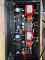
It seems that I had soldered the left UBib Led's with the wrong orientation.
Now All LED's turn on normally.
(Lesson learned, never work on a project that you have no experience at all, after 15h of work..)
Have dialed 33v on the rail and 3,93v on the tp's, after a few hours of warm up, Low MC gain.
Finally after more than 3 years in the making, it's now connected on my system and I really have no words on what difference it made.
Way better than my highly regarded and factory upgraded Bonnec phono.
Will come up on a later post with photos and listening comments.
Now letting it burn in a bit.
Will have to deeply thank Antony Katopis for giving me the idea, the resources and being such a helping hand on realizing the project, and of course Nikos Salas for his designs, all components selection, and for answering in no time on everything, even on stupid questions from people (me including) that have had no clue about electronics.
For sure this project thought me a lot on electronics and sophisticated yet austere design.
Many thanks, DCG3 will follow really soon!
First set the switches to the sensitivity you prefer. So there's a valid circuit configuration. Power on to see if something changed with voltages and lights.
If still the same:
Start with comparing the orientation of the non working Ubib Leds to the working ones in the other Ubib. Even if one is put wrong or it died by long soldering their chain breaks and no current passes.
On the lit right channel Ubib also turn its trimmer. To test for full functionality. Try adjust it down to 33V regulated output.
Congratulations for completing your UFSP successfully. Our debugging guess about wrongly oriented LED(s) luckily proved spot on. Glad to also know you like its sound contribution right out from the start. That's a good sign. Normally expect it to open up even more in the next couple of playing days as its many electrolytic caps gradually wake up from storage sleep minimizing their uA leakage current.
You are welcome. We will be expecting your fuller report with photos.
You are welcome. We will be expecting your fuller report with photos.
At raw DC points like at Ubibs inputs.
47k series protection resistor for each Led. Should give about right brightness for panel use. One or two Leds is more of an aesthetic matter. With two you typically know there's DC power in both channels for sure.
47k series protection resistor for each Led. Should give about right brightness for panel use. One or two Leds is more of an aesthetic matter. With two you typically know there's DC power in both channels for sure.
Just asking for encyclopedic reasons, what differences can someone expect from changing values on the RIAA?Congratulations for completing your UFSP successfully. Our debugging guess about wrongly oriented LED(s) luckily proved spot on. Glad to also know you like its sound contribution right out from the start. That's a good sign. Normally expect it to open up even more in the next couple of playing days as its many electrolytic caps gradually wake up from storage sleep minimizing their uA leakage current.
You are welcome. We will be expecting your fuller report with photos.
Except the HF brightness trim capacitor C2Y which I suggest you try 220pF and 330pF to decide which one suits your system better, the basic RIAA components are not to be tweaked for value. Else the correct replay of records will start going noticeably off. Only C2Y comes with pin sockets option for that reason.
Just adding my completed build to the collection. Only has about 2 hours of play on it, but wow, so much more open, detailed and effortless than my previous phono stage (Hagerman Bugle 2). Noticeably deeper darker background too. I do have a tiny bit of hiss coming through my system from it, but that’s about it.


It is a Toroidy Audio Supreme model. Vacuum impregnated windings, electric and electromagnetic shields with a polished stainless steel cover. Very nice.Is this toroidy something new? (I knew the potted ones only in glossy chrome…)
I also have a steel partition between it and the signal circuits. I was hoping all of that was sufficient to keep circuit quiet while being in the same box.
Seems to have worked - no additional hum can be heard at all while the phono input is being used.
Last edited:
- Home
- Source & Line
- Analogue Source
- Simplistic NJFET RIAA